


Request Quote
(Ships tomorrow)
FDG6318P Equivalent & Substitute Parts
Part Overview
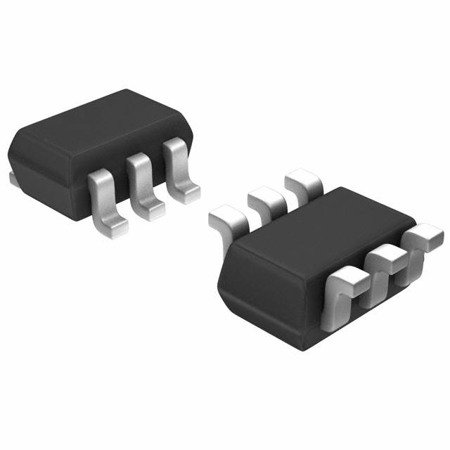
The FDG6318P is a dual P-channel MOSFET array manufactured by onsemi, designed for surface mount applications in the SC-88 (SOT-363) package. This device features logic level gate operation with a maximum drain-source voltage rating of 20V and continuous drain current capability of 500mA at 25°C. The FDG6318P is classified as obsolete product status, making identification of functionally equivalent alternatives necessary for ongoing design support and procurement continuity. Substitute parts must maintain compatibility with the SC-88/SOT-363 package footprint and satisfy the electrical performance requirements of the original design.
Substiute Parts
Key Parameters
| Parameter | Value | Unit |
|---|---|---|
| Drain to Source Voltage (Vdss) | 20 | V |
| Continuous Drain Current (Id) @ 25°C | 500 | mA |
| On-Resistance (Rds On) @ 500mA, 4.5V | 780 | mOhm |
| Gate Threshold Voltage (Vgs(th)) @ 250µA | 1.5 | V |
| Gate Charge (Qg) @ 4.5V | 1.2 | nC |
| Input Capacitance (Ciss) @ 10V | 83 | pF |
| Maximum Power Dissipation | 300 | mW |
| Operating Temperature Range | -55 to 150 | °C |
| Package Type | 6-TSSOP, SC-88, SOT-363 | — |
| Configuration | 2 P-Channel (Dual) | — |
| FET Feature | Logic Level Gate | — |
Substitute Part Grouping Explanation
Substitution eligibility for the FDG6318P is determined by the following critical parameters:
Primary Compatibility Criteria:
- Dual P-channel MOSFET configuration
- SC-88/SOT-363 package footprint
- 20V drain-source voltage rating (Vdss)
- Logic level gate operation
- Surface mount technology
Performance Compatibility Criteria:
- Continuous drain current rating equal to or greater than 500mA
- On-resistance (Rds On) at rated current and gate voltage
- Gate threshold voltage within acceptable operating range
- Operating temperature range encompassing -55°C to 150°C
The identified substitute parts NTJD4152PT1G and DMP2004DWK-7 satisfy the primary compatibility criteria and maintain the same package footprint. Both devices are dual P-channel MOSFETs with 20V Vdss ratings and logic level gate characteristics. Performance variations exist in continuous drain current capability, on-resistance characteristics, and gate charge specifications, which must be evaluated against specific application requirements.
Parameter Comparison
| Parameter | FDG6318P | NTJD4152PT1G | DMP2004DWK-7 | Unit |
|---|---|---|---|---|
| Manufacturer | onsemi | onsemi | Diodes Incorporated | — |
| Product Status | Obsolete | Active | Active | — |
| Configuration | 2 P-Channel (Dual) | 2 P-Channel (Dual) | 2 P-Channel (Dual) | — |
| Package / Case | 6-TSSOP, SC-88, SOT-363 | 6-TSSOP, SC-88, SOT-363 | 6-TSSOP, SC-88, SOT-363 | — |
| Drain to Source Voltage (Vdss) | 20 | 20 | 20 | V |
| Continuous Drain Current (Id) @ 25°C | 500 | 880 | 430 | mA |
| Rds On (Max) @ Id, 4.5V Vgs | 780 @ 500mA | 260 @ 880mA | 900 @ 430mA | mOhm |
| Gate Threshold Voltage (Vgs(th)) @ 250µA | 1.5 | 1.2 | 1.0 | V |
| Gate Charge (Qg) @ 4.5V | 1.2 | 2.2 | — | nC |
| Input Capacitance (Ciss) | 83 @ 10V | 155 @ 20V | 175 @ 16V | pF |
| Maximum Power Dissipation | 300 | 272 | 250 | mW |
| Operating Temperature Range | -55 to 150 | -55 to 150 | -65 to 150 | °C |
| FET Feature | Logic Level Gate | Logic Level Gate | Logic Level Gate | — |
| Mounting Type | Surface Mount | Surface Mount | Surface Mount | — |
| RoHS Status | — | ROHS3 Compliant | ROHS3 Compliant | — |
| Moisture Sensitivity Level (MSL) | 1 (Unlimited) | 1 (Unlimited) | 1 (Unlimited) | — |
| REACH Status | REACH Unaffected | REACH Unaffected | REACH Unaffected | — |
Engineering Selection Recommendations
NTJD4152PT1G (onsemi)
The NTJD4152PT1G is an active product offering superior electrical performance characteristics compared to the obsolete FDG6318P. This device provides 76% higher continuous drain current capability (880mA versus 500mA) and significantly lower on-resistance (260mOhm versus 780mOhm at rated conditions). The NTJD4152PT1G maintains identical voltage ratings, package compatibility, and operating temperature range. This substitute is manufactured by the same supplier as the original part, ensuring design continuity. RoHS3 compliance and REACH unaffected status confirm regulatory alignment with current environmental standards. Higher gate charge (2.2nC versus 1.2nC) and input capacitance (155pF versus 83pF) represent the performance trade-off for improved current handling capability.
DMP2004DWK-7 (Diodes Incorporated)
The DMP2004DWK-7 provides an alternative from a different manufacturer with active product status. This device maintains the same 20V voltage rating and SC-88/SOT-363 package footprint. The continuous drain current rating of 430mA falls below the original FDG6318P specification of 500mA, making this substitute suitable only for applications where the reduced current capability is acceptable. On-resistance is higher at 900mOhm compared to the original 780mOhm. The DMP2004DWK-7 offers an extended operating temperature range (-65°C to 150°C versus -55°C to 150°C) and RoHS3 compliance. This substitute is appropriate for designs with lower current requirements or where extended low-temperature operation is necessary.
Frequently Asked Questions (FAQ)
Q: Can the NTJD4152PT1G directly replace the FDG6318P in existing designs?
A: The NTJD4152PT1G is pin-compatible and functionally compatible with the FDG6318P due to identical package footprint (SC-88/SOT-363) and dual P-channel configuration. The higher current rating (880mA versus 500mA) and lower on-resistance (260mOhm versus 780mOhm) represent performance improvements. Designs operating at or below 500mA continuous drain current experience no functional degradation. Designs requiring the full 880mA capability benefit from enhanced performance margin.
Q: Is the DMP2004DWK-7 suitable as a substitute when current requirements are critical?
A: The DMP2004DWK-7 is suitable only for applications where the continuous drain current requirement does not exceed 430mA. The original FDG6318P specification of 500mA continuous drain current exceeds the DMP2004DWK-7 capability. Applications designed to operate at 430mA or below can utilize this substitute. Applications requiring the full 500mA specification must use the NTJD4152PT1G.
Q: Are there package compatibility concerns when substituting these parts?
A: All three devices utilize the 6-TSSOP/SC-88/SOT-363 package format, ensuring identical PCB footprint compatibility. No layout modifications are required for mechanical substitution. Pin assignments and functional configuration remain consistent across all three parts.
Q: What are the regulatory compliance differences between the original and substitute parts?
A: The FDG6318P does not specify RoHS status in the provided documentation. Both substitute parts (NTJD4152PT1G and DMP2004DWK-7) are RoHS3 compliant. All three devices maintain REACH unaffected status and identical moisture sensitivity level (MSL 1 - Unlimited). Both substitutes satisfy current environmental regulatory requirements.
Q: How do gate charge and input capacitance differences affect circuit performance?
A: The NTJD4152PT1G exhibits higher gate charge (2.2nC versus 1.2nC) and input capacitance (155pF versus 83pF) compared to the FDG6318P. These parameters affect gate drive circuit design and switching speed characteristics. Applications with fast switching requirements or limited gate drive capability must account for these differences. The DMP2004DWK-7 shows similarly elevated input capacitance (175pF) but does not specify gate charge.
Q: What is the significance of the lower gate threshold voltage in the substitute parts?
A: The DMP2004DWK-7 exhibits the lowest gate threshold voltage (1.0V versus 1.5V in the original), while the NTJD4152PT1G is intermediate (1.2V). Lower threshold voltages enable operation with reduced gate drive voltage, potentially improving compatibility with lower voltage logic systems. All three devices maintain logic level gate operation suitable for standard digital control circuits.
Alternative Parts

SJ6012L2TP
Littelfuse Inc.
6 Alternative Parts

JMK107BBJ476MA-RE
Taiyo Yuden
10 Alternative Parts

GMK107BBJ475MA-T
Taiyo Yuden
5 Alternative Parts
SJ6020N2ARP
Littelfuse Inc.
3 Alternative Parts
SJ6025R2ATP
Littelfuse Inc.
4 Alternative Parts

2474-05L
API Delevan Inc.
1 Alternative Parts

4590R-684K
API Delevan Inc.
1 Alternative Parts

CM6560R-334
API Delevan Inc.
1 Alternative Parts

CM6460-104
API Delevan Inc.
1 Alternative Parts

5526-12
API Delevan Inc.
1 Alternative Parts