


Request Quote
(Ships tomorrow)
FDC658AP Equivalent & Substitute Parts
Part Overview
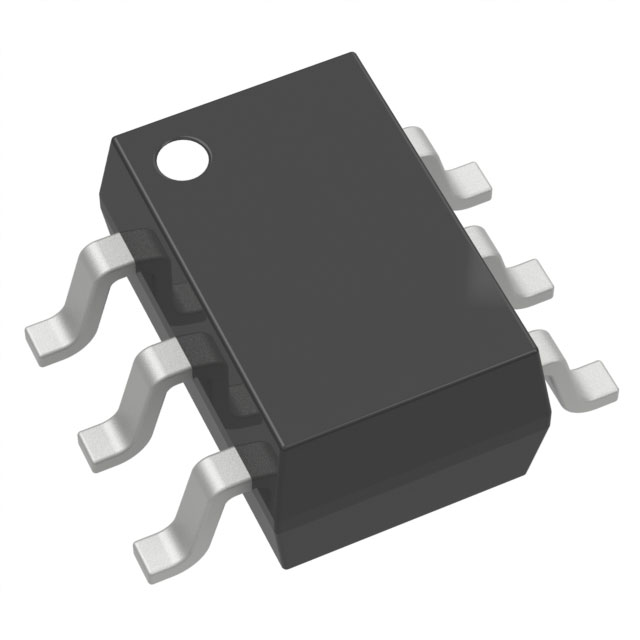
The FDC658AP is a P-Channel 30 V 4A MOSFET manufactured by onsemi in SuperSOT™-6 surface mount packaging. This device is classified as Active product status and is suitable for applications requiring moderate current switching at 30 V drain-source voltage. The part operates across an extended temperature range from -55°C to 150°C junction temperature and dissipates up to 1.6 W at ambient temperature.
Substitute parts are identified when equivalent electrical performance can be achieved within the specified parameter tolerances while maintaining compatibility with the application's thermal, mechanical, and regulatory requirements.
Substiute Parts
Key Parameters
| Parameter | FDC658AP Value | Unit |
|---|---|---|
| FET Type | P-Channel | — |
| Drain to Source Voltage (Vdss) | 30 | V |
| Continuous Drain Current (Id) @ 25°C | 4 | A |
| Rds On (Max) @ Id, Vgs | 50 mOhm @ 4A, 10V | — |
| Gate Charge (Qg) @ Vgs | 8.1 nC @ 5V | — |
| Vgs(th) (Max) @ Id | 3 V @ 250µA | — |
| Power Dissipation (Max) | 1.6 | W (Ta) |
| Operating Temperature Range | -55 to 150 | °C (TJ) |
| Package Type | SOT-23-6 Thin, TSOT-23-6 | — |
| RoHS Status | ROHS3 Compliant | — |
Substitute Part Grouping Explanation
Substitution of the FDC658AP is determined by the following critical parameters:
Electrical Compatibility Criteria:
- Drain-Source Voltage (Vdss) must equal or exceed 30 V
- Continuous Drain Current (Id) must equal or exceed 4 A at 25°C
- On-state resistance (Rds On) must not exceed 50 mOhm at rated current and 10 V gate-source voltage
- Gate threshold voltage (Vgs(th)) must be compatible with 3 V @ 250µA specification
- Gate charge (Qg) and input capacitance (Ciss) must be within acceptable switching performance parameters
Thermal and Mechanical Compatibility Criteria:
- Operating temperature range must support -55°C to 150°C junction temperature operation
- Power dissipation capability must support 1.6 W at ambient temperature minimum
- Surface mount packaging must be compatible with SOT-23-6 or equivalent 6-pin surface mount configurations
- Moisture sensitivity level must be MSL 1 (Unlimited)
Regulatory Compliance Criteria:
- RoHS3 compliance required
- REACH Unaffected status required
- ECCN EAR99 classification required
Substitute parts are grouped into two categories based on package type: SuperSOT™-6/6-CPH variants and 6-TSOP/SC-74 variants. Parts within each group maintain electrical equivalence while differing in thermal performance and gate charge characteristics.
Parameter Comparison
| Parameter | FDC658AP | CPH6341-TL-W | CPH6350-TL-W | AO6405 | BSL307SPH6327XTSA1 | DMP3050LVT-7 | PMN50EPEX | RRQ030P03TR | RRQ045P03TR | STT4P3LLH6 |
|---|---|---|---|---|---|---|---|---|---|---|
| Vdss (V) | 30 | 30 | 30 | 30 | 30 | 30 | 30 | 30 | 30 | 30 |
| Id @ 25°C (A) | 4 | 5 | 6 | 5 | 5.5 | 4.5 | 4.6 | 3 | 4.5 | 4 |
| Rds On (mOhm) @ Vgs | 50 @ 10V | 59 @ 10V | 43 @ 10V | 52 @ 10V | 43 @ 10V | 50 @ 10V | 45 @ 10V | 75 @ 10V | 35 @ 10V | 56 @ 10V |
| Qg (nC) @ Vgs | 8.1 @ 5V | 10 @ 10V | 13 @ 10V | 18 @ 10V | 29 @ 10V | 10.5 @ 10V | 20 @ 10V | 12 @ 10V | 14 @ 5V | 6 @ 4.5V |
| Vgs(th) (V) @ Id | 3 @ 250µA | — | — | 3 @ 250µA | 2 @ 40µA | 2 @ 250µA | 3 @ 250µA | 2.5 @ 1mA | 2.5 @ 1mA | 2.5 @ 250µA |
| Ciss (pF) @ Vds | 470 @ 15V | 430 @ 10V | 600 @ 10V | 840 @ 15V | 805 @ 25V | 620 @ 15V | 793 @ 15V | 480 @ 10V | 1350 @ 10V | 639 @ 25V |
| Power Dissipation (W) | 1.6 (Ta) | 1.6 (Ta) | 1.6 (Ta) | 2 (Ta) | 2 (Ta) | 1.8 (Ta) | 0.56 (Ta) | 0.6 (Ta) | 0.6 (Ta) | 1.6 (Ta) |
| Operating Temp (°C) | -55 to 150 | to 150 | to 150 | -55 to 150 | -55 to 150 | -55 to 150 | to 150 | to 150 | to 150 | to 150 |
| Package | SOT-23-6 | SOT-23-6 | SOT-23-6 | SC-74 | SC-74 | SOT-23-6 | SC-74 | SOT-23-6 | SOT-23-6 | SOT-23-6 |
| Product Status | Active | Active | Active | Not For New Designs | Active | Active | Active | Active | Not For New Designs | Active |
| RoHS Status | ROHS3 | ROHS3 | ROHS3 | ROHS3 | ROHS3 | ROHS3 | ROHS3 | ROHS3 | ROHS3 | ROHS3 |
Engineering Selection Recommendations
Primary Substitutes (Active Status, Equivalent Performance):
CPH6341-TL-W and CPH6350-TL-W are onsemi 6-CPH package variants with Active product status. CPH6341-TL-W provides 5 A continuous drain current with 59 mOhm on-state resistance, suitable for applications requiring current margin above the FDC658AP baseline. CPH6350-TL-W delivers 6 A continuous drain current with improved 43 mOhm on-state resistance, offering enhanced thermal performance for higher current applications. Both maintain 30 V Vdss rating, 1.6 W power dissipation, and full temperature range operation.
DMP3050LVT-7 (Diodes Incorporated) provides 4.5 A continuous drain current in TSOT-26 package with 50 mOhm on-state resistance and 1.8 W power dissipation. This part maintains Active product status and supports the full -55°C to 150°C operating range, offering direct electrical compatibility with enhanced thermal capability.
STT4P3LLH6 (STMicroelectronics) is an Active status part rated for 4 A continuous drain current in SOT-23-6 package with 56 mOhm on-state resistance and 1.6 W power dissipation. This device features the lowest gate charge specification (6 nC @ 4.5 V), providing reduced switching losses in high-frequency applications.
BSL307SPH6327XTSA1 (Infineon Technologies OptiMOS™ series) delivers 5.5 A continuous drain current with 43 mOhm on-state resistance in SC-74 package. Active product status and full temperature range support are provided, with enhanced current capability for demanding applications.
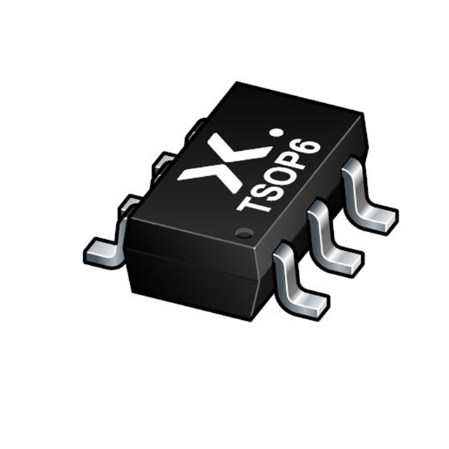
PMN50EPEX (Nexperia USA Inc.) provides 4.6 A continuous drain current with 45 mOhm on-state resistance in 6-TSOP package. Active product status is maintained with reduced power dissipation specification (560 mW Ta), suitable for thermally constrained designs.
Secondary Substitutes (Current Limitations or Obsolescence Considerations):
RRQ030P03TR (Rohm Semiconductor) is rated for 3 A continuous drain current, below the FDC658AP baseline of 4 A. This part is suitable only for applications with reduced current requirements and is not recommended for direct replacement in designs requiring full 4 A capability.
RRQ045P03TR (Rohm Semiconductor) is classified as Not For New Designs despite Active inventory status. This part provides 4.5 A continuous drain current with superior 35 mOhm on-state resistance but should not be selected for new product development.
AO6405 (Alpha & Omega Semiconductor Inc.) is classified as Not For New Designs. Although it provides 5 A continuous drain current with 52 mOhm on-state resistance and 2 W power dissipation, this obsolescence status precludes its use in new designs.
Compliance and Regulatory Status:
All listed substitute parts maintain ROHS3 compliance, REACH Unaffected status, and EAR99 ECCN classification, matching the regulatory profile of the FDC658AP. Moisture sensitivity level is MSL 1 (Unlimited) across all parts, ensuring compatibility with standard handling and storage procedures.
Frequently Asked Questions (FAQ)
Q: Can CPH6341-TL-W directly replace FDC658AP in existing designs?
A: CPH6341-TL-W is electrically compatible with FDC658AP for applications requiring up to 5 A continuous drain current. Both parts maintain 30 V Vdss rating, 1.6 W power dissipation, and equivalent gate threshold voltage characteristics. The primary difference is packaging: CPH6341-TL-W uses 6-CPH package while FDC658AP uses SuperSOT™-6. PCB layout compatibility must be verified before substitution.
Q: What is the difference between SOT-23-6 and SC-74 packages?
A: SOT-23-6 (also designated TSOT-23-6 or SuperSOT™-6) and SC-74 (also designated SOT-457 or 6-TSOP) are both 6-pin surface mount packages with different physical dimensions and thermal characteristics. SC-74 packages typically provide superior thermal performance due to larger die pad area, resulting in lower junction-to-ambient thermal resistance. PCB footprints are not interchangeable; design verification is required before package substitution.
Q: Why is RRQ045P03TR listed as Not For New Designs?
A: RRQ045P03TR carries Not For New Designs product status classification, indicating that the manufacturer has discontinued active development and support for this part. While inventory may remain available, new product designs should not incorporate this part. Alternative parts with Active status such as DMP3050LVT-7 or CPH6350-TL-W are recommended.
Q: Does gate charge (Qg) affect substitution suitability?
A: Gate charge directly impacts switching speed and driver circuit requirements. FDC658AP specifies 8.1 nC @ 5V, while substitute parts range from 6 nC (STT4P3LLH6) to 29 nC (BSL307SPH6327XTSA1). Lower gate charge reduces switching losses and driver power consumption. If the application uses a fixed gate driver with current-limited output, higher gate charge parts may require extended switching times. Driver circuit verification is necessary when substituting parts with significantly different gate charge specifications.
Q: Are all substitute parts rated for -55°C to 150°C operation?
A: No. FDC658AP, AO6405, BSL307SPH6327XTSA1, and DMP3050LVT-7 explicitly specify -55°C to 150°C operating range. CPH6341-TL-W, CPH6350-TL-W, PMN50EPEX, RRQ030P03TR, RRQ045P03TR, and STT4P3LLH6 specify only upper temperature limit (150°C) without explicit lower temperature specification. Applications requiring full -55°C to 150°C operation must select parts with complete temperature range documentation.
Q: What is the significance of on-state resistance (Rds On) variation among substitutes?
A: On-state resistance directly determines power dissipation and heat generation during conduction. FDC658AP specifies 50 mOhm @ 4A, 10V. Substitute parts range from 35 mOhm (RRQ045P03TR) to 75 mOhm (RRQ030P03TR). Lower Rds On reduces conduction losses and junction temperature rise. Higher Rds On increases power dissipation; thermal analysis must confirm that the application's thermal budget accommodates the substitute part's power dissipation characteristics.
Q: Can parts with higher continuous drain current ratings be used in place of FDC658AP?
A: Yes, provided all other electrical parameters remain compatible. Parts rated for 5 A, 5.5 A, or 6 A continuous drain current can be used in applications designed for 4 A operation. The higher current rating provides design margin and does not degrade performance. However, gate charge, input capacitance, and on-state resistance must still be verified for compatibility with the gate driver circuit and thermal requirements.
Q: What is the impact of input capacitance (Ciss) on circuit performance?
A: Input capacitance affects gate charge requirements and switching speed. FDC658AP specifies 470 pF @ 15V. Substitute parts range from 430 pF to 1350 pF. Higher input capacitance increases the charge required to switch the device and may extend switching times if the gate driver has limited current output. Applications with high switching frequency or current-limited gate drivers should prioritize parts with lower input capacitance specifications.
Q: Is inventory availability a factor in substitute part selection?
A: Inventory levels are provided for reference but should not be the primary selection criterion. FDC658AP has 41,280 pieces in stock, while some substitutes have significantly lower inventory (BSL307SPH6327XTSA1 with 1,250 pieces). Long-term product availability and supply chain stability should be evaluated through the component supplier. Parts with Active product status generally offer better long-term availability than parts classified as Not For New Designs.
Alternative Parts

SJ6012L2TP
Littelfuse Inc.
6 Alternative Parts

JMK107BBJ476MA-RE
Taiyo Yuden
10 Alternative Parts

GMK107BBJ475MA-T
Taiyo Yuden
5 Alternative Parts
SJ6020N2ARP
Littelfuse Inc.
3 Alternative Parts
SJ6025R2ATP
Littelfuse Inc.
4 Alternative Parts

2474-05L
API Delevan Inc.
1 Alternative Parts

4590R-684K
API Delevan Inc.
1 Alternative Parts

CM6560R-334
API Delevan Inc.
1 Alternative Parts

CM6460-104
API Delevan Inc.
1 Alternative Parts

5526-12
API Delevan Inc.
1 Alternative Parts