


Request Quote
(Ships tomorrow)
FDB8832-F085 Equivalent & Substitute Parts
Part Overview
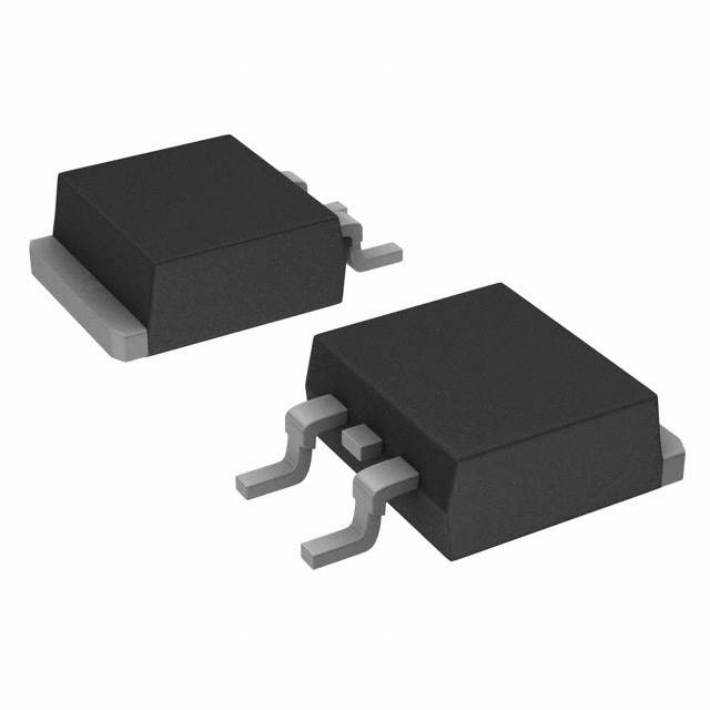
The FDB8832-F085 is an N-Channel 30V 34A MOSFET manufactured by onsemi in the PowerTrench® series, housed in a TO-263 (D2PAK) surface mount package. This device is classified as obsolete, indicating discontinuation from the manufacturer. The part delivers 300W maximum power dissipation and operates across an automotive-grade temperature range of -55°C to 175°C, with AEC-Q101 qualification. Due to its obsolete status, equivalent substitute parts with compatible electrical and mechanical specifications are necessary for ongoing design support and production continuity.
Substiute Parts
Key Parameters
| Parameter | FDB8832-F085 |
|---|---|
| Manufacturer | onsemi |
| FET Type | N-Channel |
| Drain to Source Voltage (Vdss) | 30 V |
| Continuous Drain Current (Id) @ 25°C | 34 A (Ta) |
| Rds On (Max) @ Id, Vgs | 1.9 mOhm @ 80A, 10V |
| Gate Charge (Qg) (Max) @ Vgs | 265 nC @ 10 V |
| Vgs (Max) | ±20 V |
| Power Dissipation (Max) | 300 W (Tc) |
| Operating Temperature Range | -55°C to 175°C (TJ) |
| Package / Case | TO-263-3, D2PAK (2 Leads + Tab) |
| Mounting Type | Surface Mount |
| Product Status | Obsolete |
| Grade | Automotive |
| Qualification | AEC-Q101 |
Substitute Part Grouping Explanation
Substitution of the FDB8832-F085 is determined by the following critical parameters:
Electrical Compatibility Requirements:
- Drain to Source Voltage (Vdss): Must equal or exceed 30 V
- FET Type: Must be N-Channel
- Technology: Must be MOSFET (Metal Oxide)
- Operating Temperature Range: Must span -55°C to 175°C
- Gate Voltage (Vgs Max): Must support ±20 V or greater
Mechanical Compatibility Requirements:
- Package / Case: Must be TO-263-3 or D2PAK (2 Leads + Tab) configuration
- Mounting Type: Must be Surface Mount
Performance Considerations:
- Continuous Drain Current (Id): Substitute parts with equal or higher current ratings provide functional equivalence
- Rds On (Max): Lower on-resistance values indicate improved performance characteristics
- Gate Charge (Qg): Lower gate charge values reduce switching losses
- Power Dissipation (Max): Higher power ratings provide design margin
The substitute parts listed below meet all mandatory electrical and mechanical compatibility criteria while maintaining the same package footprint and thermal characteristics.
Parameter Comparison
| Parameter | FDB8832-F085 (onsemi) | IPB80N03S4L02ATMA1 (Infineon) | PHB66NQ03LT,118 (Nexperia) | SUM90N03-2M2P-E3 (Vishay) |
|---|---|---|---|---|
| FET Type | N-Channel | N-Channel | N-Channel | N-Channel |
| Drain to Source Voltage (Vdss) | 30 V | 30 V | 25 V | 30 V |
| Continuous Drain Current (Id) @ 25°C | 34 A (Ta) | 80 A (Tc) | 66 A (Tc) | 90 A (Tc) |
| Rds On (Max) @ Id, Vgs | 1.9 mOhm @ 80A, 10V | 2.4 mOhm @ 80A, 10V | 10.5 mOhm @ 25A, 10V | 2.2 mOhm @ 32A, 10V |
| Gate Charge (Qg) (Max) @ Vgs | 265 nC @ 10 V | 140 nC @ 10 V | 12 nC @ 5 V | 257 nC @ 10 V |
| Vgs (Max) | ±20 V | ±16 V | ±20 V | ±20 V |
| Operating Temperature Range | -55°C to 175°C (TJ) | -55°C to 175°C (TJ) | -55°C to 175°C (TJ) | -55°C to 175°C (TJ) |
| Package / Case | TO-263-3, D2PAK | TO-263-3, D2PAK | TO-263-3, D2PAK | TO-263-3, D2PAK |
| Mounting Type | Surface Mount | Surface Mount | Surface Mount | Surface Mount |
| Product Status | Obsolete | Active | Obsolete | Active |
Engineering Selection Recommendations
IPB80N03S4L02ATMA1 (Infineon Technologies)
This substitute provides direct electrical and mechanical compatibility with the FDB8832-F085. The part maintains 30 V Vdss rating and offers superior continuous drain current (80 A) with comparable on-resistance (2.4 mOhm). The device is currently in active production status, ensuring long-term availability. Infineon's OptiMOS™ series technology delivers lower gate charge (140 nC) compared to the original part, reducing switching losses. The part is RoHS3 compliant and carries REACH Unaffected status. Vgs maximum rating of ±16 V is within acceptable tolerance for most applications designed for ±20 V operation. This option is recommended for applications requiring maximum current capacity and lowest switching losses.
SUM90N03-2M2P-E3 (Vishay Siliconix)
This substitute maintains full electrical and mechanical compatibility with identical 30 V Vdss and ±20 V Vgs maximum ratings. The part delivers the highest continuous drain current (90 A) among available substitutes, with on-resistance of 2.2 mOhm at 32 A. Active production status ensures availability. Vishay's TrenchFET® technology provides gate charge (257 nC) comparable to the original FDB8832-F085. The device is RoHS3 compliant. This option is recommended for applications requiring maximum current headroom and thermal margin.
PHB66NQ03LT,118 (Nexperia USA Inc.)
This substitute provides mechanical compatibility and N-Channel MOSFET functionality in the same TO-263 D2PAK package. However, the Vdss rating is 25 V, which is below the original 30 V specification. This part is suitable only for applications where the actual operating voltage does not exceed 25 V. The device is currently obsolete, limiting long-term availability. RoHS3 compliance and REACH Unaffected status are confirmed. This option is not recommended for new designs or applications requiring the full 30 V voltage rating.
Frequently Asked Questions (FAQ)
Q: Can the IPB80N03S4L02ATMA1 be used as a direct replacement for the FDB8832-F085?
A: Yes. Both devices share identical 30 V Vdss rating, N-Channel MOSFET technology, and TO-263 D2PAK package configuration. The IPB80N03S4L02ATMA1 provides higher continuous drain current (80 A versus 34 A) and lower gate charge, making it functionally superior. The ±16 V Vgs maximum is compatible with circuits designed for ±20 V operation.
Q: What is the key difference between the SUM90N03-2M2P-E3 and IPB80N03S4L02ATMA1?
A: Both maintain 30 V Vdss and TO-263 D2PAK compatibility. The SUM90N03-2M2P-E3 offers higher continuous drain current (90 A versus 80 A) and identical ±20 V Vgs maximum rating to the original part. The IPB80N03S4L02ATMA1 provides lower gate charge (140 nC versus 257 nC), resulting in reduced switching losses. Selection depends on whether the application prioritizes maximum current capacity or minimum switching losses.
Q: Why is the PHB66NQ03LT,118 not recommended as a primary substitute?
A: The PHB66NQ03LT,118 has a Vdss rating of 25 V, which is 5 V below the original FDB8832-F085 specification of 30 V. This part is suitable only for applications confirmed to operate at 25 V or below. Additionally, the part is obsolete, limiting future availability. For applications requiring the full 30 V rating, the IPB80N03S4L02ATMA1 or SUM90N03-2M2P-E3 are appropriate selections.
Q: Are all substitute parts automotive-grade?
A: The FDB8832-F085 carries automotive-grade classification with AEC-Q101 qualification. The IPB80N03S4L02ATMA1 and SUM90N03-2M2P-E3 do not explicitly list automotive qualification in the provided specifications. Applications requiring automotive-grade certification should verify qualification status with the respective manufacturers before implementation.
Q: What is the impact of lower gate charge on circuit performance?
A: Gate charge (Qg) determines the energy required to switch the MOSFET on and off. Lower gate charge reduces switching losses and allows faster switching transitions. The IPB80N03S4L02ATMA1 (140 nC) has significantly lower gate charge than the FDB8832-F085 (265 nC), resulting in improved efficiency in switching applications. The SUM90N03-2M2P-E3 (257 nC) provides comparable gate charge to the original part.
Q: Can these substitutes be used in the same PCB layout without modification?
A: Yes. All substitute parts use the TO-263 D2PAK package with identical pin configuration and footprint. No PCB layout modifications are required. However, thermal management considerations should be evaluated, as higher current ratings may affect heat dissipation requirements.
Q: What is the difference between Ta and Tc current ratings?
A: Ta (ambient temperature) and Tc (case temperature) represent different measurement conditions. The FDB8832-F085 specifies 34 A at Ta, while substitute parts specify current at Tc. These measurements reflect different thermal reference points and are not directly comparable. Actual continuous current capability depends on the specific thermal design and operating conditions of the application.
Alternative Parts

SJ6012L2TP
Littelfuse Inc.
6 Alternative Parts

JMK107BBJ476MA-RE
Taiyo Yuden
10 Alternative Parts

GMK107BBJ475MA-T
Taiyo Yuden
5 Alternative Parts
SJ6020N2ARP
Littelfuse Inc.
3 Alternative Parts
SJ6025R2ATP
Littelfuse Inc.
4 Alternative Parts

2474-05L
API Delevan Inc.
1 Alternative Parts

4590R-684K
API Delevan Inc.
1 Alternative Parts

CM6560R-334
API Delevan Inc.
1 Alternative Parts

CM6460-104
API Delevan Inc.
1 Alternative Parts

5526-12
API Delevan Inc.
1 Alternative Parts