


Request Quote
(Ships tomorrow)
FDAF75N28 Equivalent & Substitute Parts
Part Overview
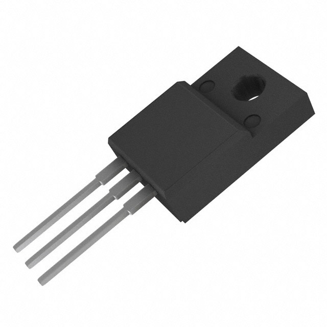
The FDAF75N28 is an N-Channel MOSFET manufactured by onsemi, rated for 280V drain-to-source voltage and 46A continuous drain current in a Through Hole TO-3PF package. This device is part of the UniFET™ series and is classified as obsolete. Due to its obsolete status, equivalent substitute parts with active product availability are necessary for new designs and ongoing production requirements. Substitute parts must maintain electrical compatibility across critical parameters including voltage rating, current capacity, and thermal characteristics while accommodating package differences.
Substiute Parts
Key Parameters
| Parameter | Value | Unit |
|---|---|---|
| FET Type | N-Channel | — |
| Technology | MOSFET (Metal Oxide) | — |
| Drain to Source Voltage (Vdss) | 280 | V |
| Current - Continuous Drain (Id) @ 25°C | 46 | A (Tc) |
| Rds On (Max) @ Id, Vgs | 41 | mOhm @ 23A, 10V |
| Power Dissipation (Max) | 215 | W (Tc) |
| Operating Temperature Range | -55 to 150 | °C (TJ) |
| Mounting Type | Through Hole | — |
| Package / Case | TO-3P-3 Full Pack | — |
Substitute Part Grouping Explanation
Substitution of the FDAF75N28 is based on electrical parameter compatibility within the N-Channel MOSFET category. The primary substitution criteria are:
Voltage Rating Compatibility: Substitute parts must have a Vdss rating equal to or greater than 280V to ensure safe operation in the original application circuit.
Current Capacity: Substitute parts must have a continuous drain current (Id) rating equal to or greater than 46A to handle the same load conditions.
On-Resistance (Rds On): Substitute parts must maintain comparable or lower on-resistance values to ensure thermal performance and efficiency are not degraded.
Power Dissipation: Substitute parts must have power dissipation ratings sufficient to handle the thermal load of the application.
Operating Temperature Range: Substitute parts must support the full operating temperature range of -55°C to 150°C (TJ).
Mounting Type: Substitute parts must be Through Hole mounted to maintain PCB compatibility.
The IXFH94N30P3 meets these criteria with a higher voltage rating (300V), significantly higher current capacity (94A), improved on-resistance (36mOhm), and substantially higher power dissipation (1040W). The package change from TO-3PF to TO-247 requires mechanical board layout verification but maintains Through Hole mounting compatibility.
Parameter Comparison
| Parameter | FDAF75N28 | IXFH94N30P3 | Unit |
|---|---|---|---|
| Manufacturer | onsemi | IXYS | — |
| Product Status | Obsolete | Active | — |
| FET Type | N-Channel | N-Channel | — |
| Technology | MOSFET (Metal Oxide) | MOSFET (Metal Oxide) | — |
| Drain to Source Voltage (Vdss) | 280 | 300 | V |
| Current - Continuous Drain (Id) @ 25°C | 46 | 94 | A (Tc) |
| Drive Voltage (Max Rds On) | 10 | 10 | V |
| Rds On (Max) @ Id, Vgs | 41 @ 23A, 10V | 36 @ 47A, 10V | mOhm |
| Vgs(th) (Max) @ Id | 5 @ 250µA | 5 @ 4mA | V |
| Gate Charge (Qg) (Max) @ Vgs | 144 @ 10V | 102 @ 10V | nC |
| Vgs (Max) | ±30 | ±20 | V |
| Input Capacitance (Ciss) (Max) @ Vds | 6700 @ 25V | 5510 @ 25V | pF |
| Power Dissipation (Max) | 215 | 1040 | W (Tc) |
| Operating Temperature Range | -55 to 150 | -55 to 150 | °C (TJ) |
| Mounting Type | Through Hole | Through Hole | — |
| Package / Case | TO-3P-3 Full Pack | TO-247-3 | — |
| Moisture Sensitivity Level (MSL) | 1 (Unlimited) | 1 (Unlimited) | — |
| REACH Status | REACH Unaffected | REACH Unaffected | — |
| ECCN | EAR99 | EAR99 | — |
| HTSUS | 8541.29.0095 | 8541.29.0095 | — |
Engineering Selection Recommendations
The IXFH94N30P3 is an active product substitute for the obsolete FDAF75N28. Selection of this substitute is supported by the following factors:
Product Status: The IXFH94N30P3 maintains active product status with current manufacturing and supply chain availability, eliminating obsolescence risk associated with the FDAF75N28.
Regulatory Compliance: Both devices share identical REACH and ECCN classifications (REACH Unaffected, EAR99), ensuring no additional regulatory burden in substitution. Both devices carry MSL Level 1 (Unlimited) moisture sensitivity ratings.
Electrical Superiority: The IXFH94N30P3 exceeds the FDAF75N28 across all critical electrical parameters. The 300V Vdss rating provides 7% margin above the original 280V specification. The 94A continuous drain current rating provides 104% additional capacity beyond the original 46A specification. The 36mOhm on-resistance at 47A represents improved efficiency compared to the 41mOhm specification at 23A.
Thermal Performance: The 1040W power dissipation rating of the IXFH94N30P3 provides substantially greater thermal headroom than the 215W rating of the FDAF75N28, enabling operation in higher-power applications or with reduced thermal management requirements.
Temperature Range: Both devices support the identical operating temperature range of -55°C to 150°C (TJ), ensuring thermal compatibility across all application environments.
Package Consideration: The substitution requires a package change from TO-3PF to TO-247. This change necessitates PCB layout modification to accommodate the different pin configuration and mechanical footprint of the TO-247 package. Pin assignment verification is required during board redesign.
Frequently Asked Questions (FAQ)
Q: Can the IXFH94N30P3 directly replace the FDAF75N28 without circuit modification?
A: The IXFH94N30P3 is electrically compatible with the FDAF75N28 across all critical parameters. However, the package change from TO-3PF to TO-247 requires PCB layout modification. Pin assignments must be verified and the board footprint must be redesigned to accommodate the TO-247 package geometry. No circuit schematic changes are required if the application operates within the original electrical specifications.
Q: What are the key electrical advantages of the IXFH94N30P3 over the FDAF75N28?
A: The IXFH94N30P3 provides three primary electrical advantages: (1) Higher voltage rating of 300V versus 280V, providing additional design margin; (2) Doubled continuous drain current capacity of 94A versus 46A, enabling higher-power applications; (3) Lower on-resistance of 36mOhm versus 41mOhm, resulting in reduced power dissipation and improved efficiency.
Q: Are there thermal management differences between these devices?
A: Yes. The IXFH94N30P3 has a maximum power dissipation rating of 1040W compared to 215W for the FDAF75N28. This 4.8x increase in power dissipation capability allows the IXFH94N30P3 to operate in higher-power applications or with less aggressive thermal management. Both devices operate across the same temperature range of -55°C to 150°C (TJ).
Q: What is the impact of the package change from TO-3PF to TO-247?
A: The package change affects only the physical board layout and mechanical mounting. The TO-247 package has a different pin configuration and footprint compared to the TO-3P-3 Full Pack. PCB redesign is required to accommodate the new package geometry. Both packages are Through Hole mounted, maintaining compatibility with existing assembly processes. Electrical performance is not affected by the package change.
Q: Are there any compliance or regulatory differences between the FDAF75N28 and IXFH94N30P3?
A: No. Both devices share identical regulatory classifications: REACH Unaffected status, EAR99 ECCN classification, and 8541.29.0095 HTSUS code. Both devices carry MSL Level 1 (Unlimited) moisture sensitivity ratings. No additional compliance documentation or certifications are required for substitution.
Q: What gate charge differences exist between these devices?
A: The IXFH94N30P3 has a maximum gate charge of 102 nC at 10V, compared to 144 nC for the FDAF75N28. The lower gate charge of the substitute device results in faster switching characteristics and reduced gate drive power requirements, providing improved circuit efficiency.
Q: Are the input capacitance values significantly different?
A: The IXFH94N30P3 has an input capacitance (Ciss) of 5510 pF at 25V, compared to 6700 pF for the FDAF75N28. The 18% reduction in input capacitance contributes to faster switching performance and lower gate drive requirements in the substitute device.
Q: What is the maximum gate voltage difference between these devices?
A: The FDAF75N28 supports a maximum gate voltage (Vgs) of ±30V, while the IXFH94N30P3 supports ±20V. If the original application uses gate voltages exceeding ±20V, circuit modification is required to limit gate voltage to the ±20V maximum of the substitute device.
Alternative Parts

SJ6012L2TP
Littelfuse Inc.
6 Alternative Parts

JMK107BBJ476MA-RE
Taiyo Yuden
10 Alternative Parts

GMK107BBJ475MA-T
Taiyo Yuden
5 Alternative Parts
SJ6020N2ARP
Littelfuse Inc.
3 Alternative Parts
SJ6025R2ATP
Littelfuse Inc.
4 Alternative Parts

2474-05L
API Delevan Inc.
1 Alternative Parts

4590R-684K
API Delevan Inc.
1 Alternative Parts

CM6560R-334
API Delevan Inc.
1 Alternative Parts

CM6460-104
API Delevan Inc.
1 Alternative Parts

5526-12
API Delevan Inc.
1 Alternative Parts