


Request Quote
(Ships tomorrow)
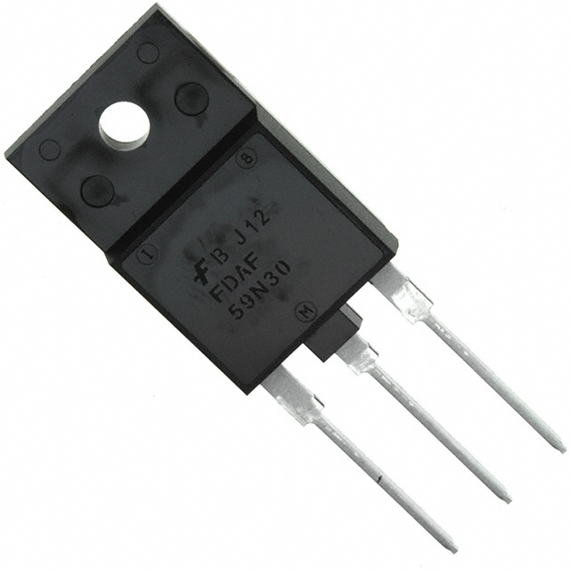
FDAF59N30 Equivalent & Substitute Parts
Part Overview
The FDAF59N30 is an N-Channel MOSFET manufactured by onsemi, rated for 300V drain-to-source voltage with 34A continuous drain current at 25°C. This device is packaged in a TO-3PF through-hole configuration and is part of the UniFET™ series. The FDAF59N30 is classified as obsolete, making identification of equivalent and substitute parts essential for design continuity and procurement planning. Substitute parts must maintain electrical compatibility across voltage, current, and thermal specifications while accommodating potential package variations.
Substiute Parts
Key Parameters
| Parameter | Value | Unit |
|---|---|---|
| FET Type | N-Channel | — |
| Drain to Source Voltage (Vdss) | 300 | V |
| Current - Continuous Drain (Id) @ 25°C | 34 | A (Tc) |
| Rds On (Max) @ Id, Vgs | 56 mOhm @ 17A, 10V | — |
| Drive Voltage (Max Rds On) | 10 | V |
| Vgs(th) (Max) @ Id | 5 | V @ 250µA |
| Gate Charge (Qg) (Max) @ Vgs | 100 | nC @ 10V |
| Vgs (Max) | ±30 | V |
| Input Capacitance (Ciss) (Max) @ Vds | 4670 | pF @ 25V |
| Power Dissipation (Max) | 161 | W (Tc) |
| Operating Temperature | -55 to 150 | °C (TJ) |
| Mounting Type | Through Hole | — |
| Package / Case | TO-3P-3 Full Pack | — |
| Product Status | Obsolete | — |
Substitute Part Grouping Explanation
Substitution of the FDAF59N30 is determined by strict adherence to the following electrical and mechanical parameters:
Primary Substitution Criteria:
- Drain to Source Voltage (Vdss): Must equal or exceed 300V
- FET Type: Must be N-Channel MOSFET
- Current - Continuous Drain (Id) @ 25°C: Must equal or exceed 34A
- Rds On (Max) @ Id, Vgs: Must not exceed 56 mOhm at the specified gate voltage
- Drive Voltage: Must support 10V gate drive
- Vgs (Max): Must accommodate ±30V or greater
- Operating Temperature Range: Must span -55°C to 150°C (TJ)
- Mounting Type: Must be Through Hole
Secondary Compatibility Factors:
- Gate Charge (Qg): Lower values indicate faster switching; higher values are acceptable
- Input Capacitance (Ciss): Variations acceptable within circuit design margins
- Power Dissipation (Max): Higher ratings provide thermal margin
- Package compatibility: Physical footprint differences require PCB layout evaluation
The substitute parts listed below meet or exceed all primary criteria. Package variations (TO-247 vs. TO-3PF) represent mechanical differences that require board-level assessment but do not affect electrical substitution validity.
Parameter Comparison
| Parameter | FDAF59N30 (onsemi) | IXFH40N30 (IXYS) | AOK60N30L (Alpha & Omega) |
|---|---|---|---|
| Drain to Source Voltage (Vdss) | 300 V | 300 V | 300 V |
| Current - Continuous Drain (Id) @ 25°C | 34 A (Tc) | 40 A (Tc) | 60 A (Tc) |
| Rds On (Max) @ Id, Vgs | 56 mOhm @ 17A, 10V | 85 mOhm @ 500mA, 10V | 56 mOhm @ 30A, 10V |
| Drive Voltage (Max Rds On) | 10 V | 10 V | 10 V |
| Vgs(th) (Max) @ Id | 5 V @ 250µA | 4 V @ 4mA | 4.1 V @ 250µA |
| Gate Charge (Qg) (Max) @ Vgs | 100 nC @ 10V | 200 nC @ 10V | 106 nC @ 10V |
| Vgs (Max) | ±30 V | ±20 V | ±30 V |
| Input Capacitance (Ciss) (Max) @ Vds | 4670 pF @ 25V | 4800 pF @ 25V | 5330 pF @ 25V |
| Power Dissipation (Max) | 161 W (Tc) | 300 W (Tc) | 658 W (Tc) |
| Operating Temperature | -55 to 150 °C (TJ) | -55 to 150 °C (TJ) | -55 to 150 °C (TJ) |
| Mounting Type | Through Hole | Through Hole | Through Hole |
| Package / Case | TO-3P-3 Full Pack | TO-247-3 | TO-247-3 |
| Product Status | Obsolete | Active | Obsolete |
| RoHS Status | Not specified | ROHS3 Compliant | Not specified |
Engineering Selection Recommendations
IXFH40N30 (IXYS HiPerFET™ Series)
The IXFH40N30 is the preferred substitute for new designs and procurement. This device maintains 300V Vdss and 40A continuous drain current, exceeding the FDAF59N30 specification by 6A. The IXFH40N30 carries Active product status, ensuring long-term availability and supply chain stability. ROHS3 compliance provides regulatory alignment for modern manufacturing environments. The TO-247-3 package is mechanically compatible with standard through-hole PCB layouts, though pin configuration must be verified against the original TO-3PF footprint. Higher power dissipation (300W vs. 161W) provides thermal margin in applications approaching current limits.
AOK60N30L (Alpha & Omega Semiconductor)
The AOK60N30L offers the highest current rating (60A) and power dissipation (658W) among available substitutes, providing maximum thermal and electrical headroom. This device maintains 300V Vdss and matches the 56 mOhm Rds On specification at higher current levels (30A vs. 17A). The TO-247-3 package is standard for high-current applications. However, AOK60N30L carries Obsolete product status, limiting long-term procurement viability. This substitute is suitable for immediate replacement in existing production runs but should not be selected for new designs requiring extended component availability.
Regulatory and Compliance Considerations
Both substitute parts maintain REACH Unaffected status and EAR99 ECCN classification, matching the original FDAF59N30 regulatory profile. IXFH40N30 ROHS3 compliance exceeds the original specification, supporting modern supply chain requirements. Moisture Sensitivity Level (MSL) remains 1 (Unlimited) across all parts, eliminating moisture-related handling constraints.
Frequently Asked Questions (FAQ)
Q: Can the IXFH40N30 directly replace the FDAF59N30 without circuit modification?
A: Electrical substitution is valid based on matching Vdss (300V), exceeding Id (40A vs. 34A), and maintaining compatible gate drive voltage (10V). However, package differences between TO-3PF and TO-247-3 require PCB layout evaluation. Pin assignments must be verified against the original schematic to ensure correct gate, drain, and source connections. Thermal management may differ due to package geometry variations.
Q: What is the significance of the Rds On specification difference between FDAF59N30 (56 mOhm @ 17A) and IXFH40N30 (85 mOhm @ 500mA)?
A: Rds On is measured at different current levels, reflecting device characterization methodology rather than performance degradation. The IXFH40N30 specification at 500mA represents a lower current measurement point. At the FDAF59N30 operating current (17A), the IXFH40N30 Rds On would be lower than the specified 85 mOhm value. Direct comparison requires normalized measurement conditions; however, both devices meet the 56 mOhm threshold at 10V gate drive.
Q: Is the AOK60N30L suitable for new product designs?
A: The AOK60N30L is not recommended for new designs due to Obsolete product status. While electrical specifications exceed FDAF59N30 requirements, obsolete classification indicates discontinued manufacturing and limited future availability. The IXFH40N30, with Active status, provides superior long-term supply chain security for new development.
Q: What are the package-related considerations when substituting TO-3PF with TO-247-3?
A: TO-3PF and TO-247-3 are distinct through-hole packages with different physical dimensions and pin configurations. TO-247-3 is more compact and widely used in modern power electronics. PCB footprint compatibility must be verified; existing TO-3PF layouts may require redesign to accommodate TO-247-3 mounting holes and lead spacing. Thermal interface requirements may differ, affecting heatsink mounting strategies.
Q: Does the higher Gate Charge (Qg) of IXFH40N30 (200 nC vs. 100 nC) affect circuit performance?
A: Higher gate charge increases the energy required to switch the device and may extend switching time in gate-drive-limited applications. For circuits with adequate gate drive capability (10V specified), this difference is typically accommodated within design margins. Applications with marginal gate drive current capacity should evaluate switching frequency impact and driver power dissipation.
Q: Are there thermal management differences between the substitute parts?
A: Power dissipation ratings differ significantly: FDAF59N30 (161W), IXFH40N30 (300W), and AOK60N30L (658W). Higher ratings indicate greater thermal capacity but do not mandate increased heatsinking. Actual thermal performance depends on junction-to-case resistance, heatsink interface, and ambient conditions. Package geometry (TO-3PF vs. TO-247-3) affects thermal interface area and mounting configuration.
Q: Can the FDAF59N30 be used in applications designed for the IXFH40N30?
A: No. The FDAF59N30 is rated for 34A continuous current, while IXFH40N30 is rated for 40A. Using the lower-rated device in a 40A application exceeds its continuous current specification, risking thermal runaway and device failure. Substitution must always proceed from lower-rated to higher-rated devices to maintain design safety margins.
Alternative Parts

SJ6012L2TP
Littelfuse Inc.
6 Alternative Parts

JMK107BBJ476MA-RE
Taiyo Yuden
10 Alternative Parts

GMK107BBJ475MA-T
Taiyo Yuden
5 Alternative Parts
SJ6020N2ARP
Littelfuse Inc.
3 Alternative Parts
SJ6025R2ATP
Littelfuse Inc.
4 Alternative Parts

2474-05L
API Delevan Inc.
1 Alternative Parts

4590R-684K
API Delevan Inc.
1 Alternative Parts

CM6560R-334
API Delevan Inc.
1 Alternative Parts

CM6460-104
API Delevan Inc.
1 Alternative Parts

5526-12
API Delevan Inc.
1 Alternative Parts