


Request Quote
(Ships tomorrow)
FCP9N60N-F102 Equivalent & Substitute Parts
Part Overview
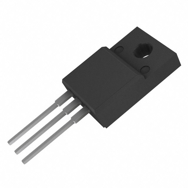
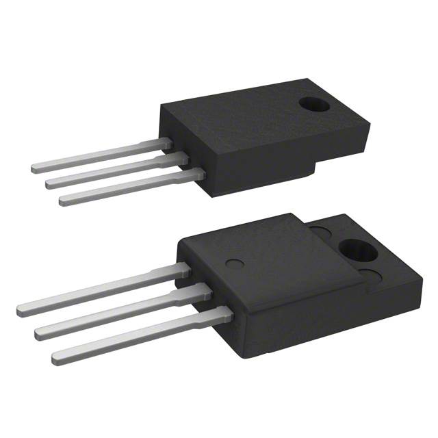
The FCP9N60N-F102 is an N-Channel 600V 9A MOSFET manufactured by onsemi in a Through Hole TO-220F package. This device is classified as Obsolete, necessitating identification of equivalent and substitute components for ongoing applications. The part delivers 83.3W maximum power dissipation and operates across the temperature range of -55°C to 150°C. Due to its obsolete status, alternative parts with compatible electrical and mechanical characteristics are required for design continuity and procurement.
Substiute Parts
Key Parameters
| Parameter | Value | Unit |
|---|---|---|
| FET Type | N-Channel | — |
| Drain to Source Voltage (Vdss) | 600 | V |
| Continuous Drain Current (Id) @ 25°C | 9 | A |
| Rds On (Max) @ Id, Vgs | 385 mOhm @ 4.5A, 10V | — |
| Gate Charge (Qg) @ Vgs | 29 nC @ 10V | — |
| Vgs (Max) | ±30 | V |
| Input Capacitance (Ciss) @ Vds | 1240 pF @ 100V | — |
| Power Dissipation (Max) | 83.3 | W |
| Operating Temperature Range | -55 to 150 | °C |
| Mounting Type | Through Hole | — |
| Package / Case | TO-220-3 Full Pack | — |
| RoHS Status | ROHS3 Compliant | — |
Substitute Part Grouping Explanation
Substitution of the FCP9N60N-F102 is determined by alignment of the following critical electrical and mechanical parameters:
Voltage Rating Compatibility: Substitute parts must maintain a Drain to Source Voltage (Vdss) rating of 600V or higher to ensure safe operation within the original design envelope.
Current Rating Compatibility: Continuous Drain Current (Id) at 25°C must equal or exceed 9A to support the original circuit load requirements.
On-State Resistance (Rds On): The maximum on-state resistance must be compatible with thermal and efficiency constraints of the application. Parts with Rds On values within reasonable engineering tolerance of 385 mOhm are considered suitable.
Gate Charge (Qg): Gate charge values determine switching speed and driver circuit compatibility. Substitute parts with gate charge in the range of 11 nC to 68 nC are acceptable within the scope of this analysis.
Package and Mounting: All substitute parts must use Through Hole mounting in TO-220-3 Full Pack or equivalent mechanical configuration to ensure PCB compatibility.
Temperature Range: Operating temperature range of -55°C to 150°C must be maintained across all substitute options.
Compliance: All substitute parts must maintain ROHS3 compliance and REACH Unaffected status consistent with the original part.
Parameter Comparison
| Parameter | FCP9N60N-F102 | FCP360N65S3R0 | AOTF11S60L | AOTF11S65L | AOTF18N65 | IPA60R380E6XKSA1 | IXFP12N65X2M | STFU15NM65N |
|---|---|---|---|---|---|---|---|---|
| Manufacturer | onsemi | onsemi | Alpha & Omega | Alpha & Omega | Alpha & Omega | Infineon | IXYS | STMicroelectronics |
| Vdss (V) | 600 | 650 | 600 | 650 | 650 | 600 | 650 | 650 |
| Id @ 25°C (A) | 9 | 10 | 11 | 11 | 18 | 10.6 | 12 | 12 |
| Rds On (Max) (mOhm) | 385 @ 4.5A, 10V | 360 @ 5A, 10V | 399 @ 3.8A, 10V | 399 @ 5.5A, 10V | 390 @ 9A, 10V | 380 @ 3.8A, 10V | 310 @ 6A, 10V | 380 @ 6A, 10V |
| Qg @ 10V (nC) | 29 | 18 | 11 | 13.2 | 68 | 32 | 18.5 | 33.3 |
| Vgs (Max) (V) | ±30 | ±30 | ±30 | ±30 | ±30 | ±20 | ±30 | ±25 |
| Ciss @ Vds (pF) | 1240 @ 100V | 730 @ 400V | 545 @ 100V | 646 @ 100V | 3785 @ 25V | 700 @ 100V | 1134 @ 25V | 983 @ 50V |
| Power Dissipation (Max) (W) | 83.3 | 83 | 38 | 31 | 50 | 31 | 40 | 30 |
| Operating Temp Range (°C) | -55 to 150 | -55 to 150 | -55 to 150 | -55 to 150 | -55 to 150 | -55 to 150 | -55 to 150 | -55 to 150 |
| Package | TO-220-3 Full Pack | TO-220-3 | TO-220-3 Full Pack | TO-220-3 Full Pack | TO-220-3 Full Pack | TO-220-3 Full Pack | TO-220-3 Full Pack, Isolated Tab | TO-220-3 Full Pack |
| Product Status | Obsolete | Not For New Designs | Active | Active | Active | Not For New Designs | Active | Active |
| RoHS Status | ROHS3 Compliant | ROHS3 Compliant | ROHS3 Compliant | ROHS3 Compliant | ROHS3 Compliant | ROHS3 Compliant | ROHS3 Compliant | ROHS3 Compliant |
Engineering Selection Recommendations
Primary Recommendation: AOTF11S60L
The AOTF11S60L from Alpha & Omega Semiconductor Inc. is the preferred substitute for the FCP9N60N-F102. This part maintains the 600V voltage rating, exceeds the 9A current requirement with 11A continuous drain current, and delivers superior on-state resistance of 399 mOhm. The gate charge of 11 nC is significantly lower than the original 29 nC, enabling faster switching characteristics. The part carries Active product status, ensuring long-term availability and supply chain stability. ROHS3 compliance and REACH Unaffected status are maintained. The TO-220-3 Full Pack configuration provides direct mechanical compatibility.
Secondary Recommendation: AOTF11S65L
The AOTF11S65L offers a 650V voltage rating with 11A continuous drain current and 399 mOhm on-state resistance. This part provides additional voltage margin for applications requiring enhanced overvoltage protection. Gate charge of 13.2 nC remains favorable for switching performance. Active product status and full compliance certifications are maintained. The TO-220-3 Full Pack package ensures mechanical compatibility.
Alternative Recommendation: IXFP12N65X2M
The IXFP12N65X2M from IXYS provides 650V voltage rating with 12A continuous drain current and superior on-state resistance of 310 mOhm. This part delivers the lowest on-state resistance among all substitutes, resulting in reduced conduction losses. Gate charge of 18.5 nC supports efficient switching. Active product status and full compliance certifications apply. The TO-220-3 Full Pack with Isolated Tab configuration provides mechanical compatibility with potential thermal performance benefits.
Acceptable Alternatives: FCP360N65S3R0, IPA60R380E6XKSA1, STFU15NM65N
These parts meet the electrical and mechanical substitution criteria but carry "Not For New Designs" product status (FCP360N65S3R0, IPA60R380E6XKSA1) or represent alternative technology platforms. They are suitable for replacement in existing designs but should not be selected for new development programs.
Not Recommended: AOTF18N65
While the AOTF18N65 meets voltage and current requirements, its gate charge of 68 nC and power dissipation of 50W represent significant deviations from the original part characteristics. This part is suitable only for applications where higher current capacity is required.
Frequently Asked Questions (FAQ)
Q: Can the FCP9N60N-F102 be directly replaced with any of these substitute parts?
A: Direct replacement is possible with AOTF11S60L, AOTF11S65L, IXFP12N65X2M, and STFU15NM65N due to identical TO-220-3 Full Pack mechanical configuration and compatible electrical parameters. All parts maintain the same mounting footprint and pin configuration. Verification of gate drive circuit compatibility is recommended due to variations in gate charge.
Q: What is the significance of the gate charge (Qg) difference between the original part and substitutes?
A: Gate charge determines the energy required to switch the MOSFET on and off. The FCP9N60N-F102 has 29 nC gate charge. Substitutes with lower gate charge (AOTF11S60L at 11 nC, IXFP12N65X2M at 18.5 nC) enable faster switching and reduced driver power dissipation. Substitutes with higher gate charge (AOTF18N65 at 68 nC) require more driver energy but do not prevent substitution if the gate driver circuit has sufficient current capability.
Q: Why do some substitute parts have higher voltage ratings (650V vs. 600V)?
A: Higher voltage ratings provide additional safety margin for transient overvoltage conditions and allow operation in applications with higher supply voltages. A 650V rated part can be used in any 600V application without derating. The higher voltage rating does not negatively impact performance in 600V circuits.
Q: What is the difference between TO-220-3 Full Pack and TO-220-3 Full Pack with Isolated Tab?
A: Both configurations use the same three-pin TO-220 footprint. The Isolated Tab variant (IXFP12N65X2M) features a thermally isolated mounting tab that does not conduct electrical current to the case, providing additional design flexibility in some applications. Standard TO-220-3 Full Pack parts have the tab electrically connected to the drain. Both are mechanically compatible with standard TO-220 PCB layouts.
Q: Are there any compliance or certification differences between the original part and substitutes?
A: All substitute parts maintain ROHS3 compliance and REACH Unaffected status consistent with the FCP9N60N-F102. No compliance degradation occurs with any recommended substitute. All parts are suitable for applications requiring environmental and regulatory compliance.
Q: What does "Not For New Designs" product status mean?
A: Parts with "Not For New Designs" status (FCP360N65S3R0, IPA60R380E6XKSA1) are available for replacement and repair of existing products but are not recommended for incorporation into new designs. These parts may have limited long-term availability or have been superseded by newer technology. Active status parts (AOTF11S60L, AOTF11S65L, IXFP12N65X2M, STFU15NM65N) are recommended for new designs.
Q: How does on-state resistance (Rds On) affect circuit performance?
A: On-state resistance determines conduction losses when the MOSFET is in the on state. Lower Rds On values reduce power dissipation and heat generation. The FCP9N60N-F102 has 385 mOhm Rds On. Substitutes with lower Rds On (IXFP12N65X2M at 310 mOhm, FCP360N65S3R0 at 360 mOhm) improve efficiency. Substitutes with comparable or slightly higher Rds On (AOTF11S60L at 399 mOhm) have negligible impact on circuit performance.
Q: Can the continuous drain current rating be exceeded in applications?
A: No. The continuous drain current rating (9A for the original part) represents the maximum sustained current at 25°C case temperature. Exceeding this rating results in excessive junction temperature and device failure. Substitute parts with higher current ratings (10A to 18A) provide additional current capacity margin but should not be used to exceed the original circuit design current limits.
Q: What inventory considerations apply to these substitute parts?
A: The FCP9N60N-F102 is obsolete with 1013 pieces in stock. AOTF11S60L has the highest inventory at 19,825 pieces, providing excellent long-term availability. AOTF11S65L has 6,030 pieces, AOTF18N65 has 10,226 pieces, and IXFP12N65X2M has 1,395 pieces. FCP360N65S3R0 has 1,284 pieces. These inventory levels support both immediate replacement needs and future procurement requirements.
Alternative Parts

SJ6012L2TP
Littelfuse Inc.
6 Alternative Parts

JMK107BBJ476MA-RE
Taiyo Yuden
10 Alternative Parts

GMK107BBJ475MA-T
Taiyo Yuden
5 Alternative Parts
SJ6020N2ARP
Littelfuse Inc.
3 Alternative Parts
SJ6025R2ATP
Littelfuse Inc.
4 Alternative Parts

2474-05L
API Delevan Inc.
1 Alternative Parts

4590R-684K
API Delevan Inc.
1 Alternative Parts

CM6560R-334
API Delevan Inc.
1 Alternative Parts

CM6460-104
API Delevan Inc.
1 Alternative Parts

5526-12
API Delevan Inc.
1 Alternative Parts