


Request Quote
(Ships tomorrow)
FCP9N60N N-Channel MOSFET 600V 9A Equivalent & Substitute Parts
Part Overview
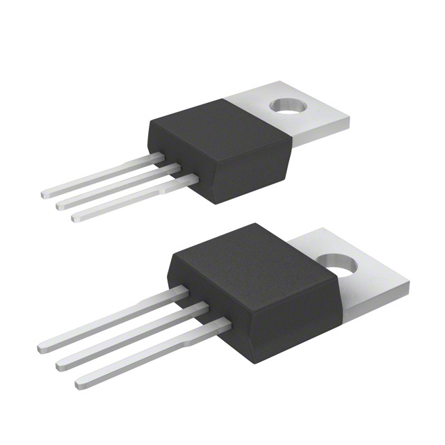
The FCP9N60N is an N-Channel MOSFET manufactured by onsemi, rated for 600V drain-to-source voltage and 9A continuous drain current in a TO-220-3 through-hole package. This device belongs to the SuperMOS™ series and is classified as obsolete. Due to its obsolete status, equivalent and substitute parts from active product lines are necessary for new designs and ongoing production requirements. Substitute parts must maintain electrical compatibility within the specified parameter ranges while accommodating the through-hole TO-220-3 package format.
Substiute Parts
Key Parameters
| Parameter | FCP9N60N Value | Unit |
|---|---|---|
| Drain-to-Source Voltage (Vdss) | 600 | V |
| Continuous Drain Current (Id) @ 25°C | 9 | A |
| On-State Resistance (Rds On) @ 4.5A, 10V | 385 | mOhm |
| Gate Threshold Voltage (Vgs(th)) @ 250µA | 4 | V |
| Gate Charge (Qg) @ 10V | 29 | nC |
| Input Capacitance (Ciss) @ 100V | 1240 | pF |
| Power Dissipation (Max) | 83.3 | W |
| Operating Temperature Range | -55 to 150 | °C |
| Package Type | TO-220-3 | Through Hole |
| FET Type | N-Channel | — |
| Technology | MOSFET (Metal Oxide) | — |
Substitute Part Grouping Explanation
Substitution of the FCP9N60N is determined by the following critical parameters:
Electrical Compatibility Criteria:
- Drain-to-Source Voltage (Vdss): Substitute parts must equal or exceed 600V
- Continuous Drain Current (Id): Substitute parts must equal or exceed 9A at 25°C
- Gate Drive Voltage: Substitute parts must operate at 10V drive voltage
- Operating Temperature Range: Substitute parts must span -55°C to 150°C
- FET Type: All substitutes must be N-Channel MOSFETs
Mechanical Compatibility Criteria:
- Package Type: All substitutes must use TO-220-3 through-hole package format
- Mounting Type: Through-hole configuration required
Compliance Criteria:
- RoHS3 Compliance: Required
- REACH Status: Unaffected or compliant
Substitute parts are grouped into two categories: MFR Recommended (manufacturer-endorsed alternatives) and Similar (functionally equivalent parts from other manufacturers that meet or exceed the specified electrical and mechanical parameters).
Parameter Comparison
| Parameter | FCP9N60N | FCP360N65S3R0 | AOT11S60L | IPP60R299CPXKSA1 | IXTP12N65X2 | STP13N60M2 | STP13NM60N | STP13NM60ND | STP15N80K5 | STP17N80K5 | Unit |
|---|---|---|---|---|---|---|---|---|---|---|---|
| Manufacturer | onsemi | onsemi | Alpha & Omega | Infineon | IXYS | STMicroelectronics | STMicroelectronics | STMicroelectronics | STMicroelectronics | STMicroelectronics | — |
| Vdss | 600 | 650 | 600 | 650 | 650 | 600 | 600 | 600 | 800 | 800 | V |
| Id @ 25°C | 9 | 10 | 11 | 11 | 12 | 11 | 11 | 11 | 14 | 14 | A |
| Rds On (Max) @ 10V | 385 | 360 | 399 | 299 | 300 | 380 | 360 | 380 | 375 | 340 | mOhm |
| Vgs(th) (Max) | 4 | 4.5 | 4.1 | 3.5 | 5 | 4 | 4 | 5 | 5 | 5 | V |
| Gate Charge (Qg) @ 10V | 29 | 18 | 11 | 29 | 17 | 17 | 30 | 24.5 | 32 | 26 | nC |
| Ciss @ 100V | 1240 | 730 | 545 | 1100 | 1100 | 580 | 790 | 845 | 1100 | 866 | pF |
| Power Dissipation (Max) | 83.3 | 83 | 178 | 96 | 180 | 110 | 90 | 109 | 190 | 170 | W |
| Operating Temperature | -55 to 150 | -55 to 150 | -55 to 150 | -55 to 150 | -55 to 150 | -55 to 150 | -55 to 150 | -55 to 150 | -55 to 150 | -55 to 150 | °C |
| Package | TO-220-3 | TO-220-3 | TO-220-3 | PG-TO220-3 | TO-220-3 | TO-220-3 | TO-220-3 | TO-220-3 | TO-220-3 | TO-220-3 | — |
| Product Status | Obsolete | Not For New Designs | Not For New Designs | Not For New Designs | Active | Active | Active | Active | Active | Active | — |
| RoHS3 Compliance | Yes | Yes | Yes | Yes | Yes | Yes | Yes | Yes | Yes | Yes | — |
Engineering Selection Recommendations
For New Designs:
Active product status is the primary criterion for new design selection. The following parts carry active product status and are suitable for new applications:
-
IXTP12N65X2 (IXYS): Active status, 650V/12A, improved on-state resistance (300 mOhm), reduced gate charge (17 nC), higher power dissipation capability (180W). Suitable for applications requiring enhanced thermal performance.
-
STP13N60M2 (STMicroelectronics): Active status, 600V/11A, MDmesh™ II Plus series, gate charge 17 nC, power dissipation 110W. Direct voltage class match with improved current rating.
-
STP13NM60N (STMicroelectronics): Active status, 600V/11A, MDmesh™ II series, on-state resistance 360 mOhm, power dissipation 90W. Optimized for lower conduction losses.
-
STP13NM60ND (STMicroelectronics): Active status, 600V/11A, FDmesh™ II series, gate charge 24.5 nC, power dissipation 109W. Balanced performance characteristics.
-
STP15N80K5 (STMicroelectronics): Active status, 800V/14A, SuperMESH5™ series. Suitable for applications requiring higher voltage margin and increased current capacity.
-
STP17N80K5 (STMicroelectronics): Active status, 800V/14A, MDmesh™ K5 series, lowest on-state resistance (340 mOhm), reduced gate charge (26 nC). Optimal for high-efficiency applications.
For Replacement in Existing Designs:
- FCP360N65S3R0 (onsemi): Manufacturer-recommended alternative, 650V/10A, SuperFET® III series. Maintains onsemi ecosystem compatibility with improved specifications.
Compliance Verification:
All substitute parts maintain RoHS3 compliance and REACH unaffected status, matching the original FCP9N60N certification requirements.
Frequently Asked Questions (FAQ)
Q: Can I use a substitute part with higher Vdss rating than the FCP9N60N?
A: Yes. Substitute parts with Vdss ratings of 650V or 800V are electrically compatible with applications designed for 600V operation. Higher voltage ratings provide additional safety margin and do not degrade performance in 600V circuits.
Q: What is the significance of on-state resistance (Rds On) differences between substitute parts?
A: Rds On directly affects conduction losses and heat generation. Lower Rds On values (such as 299 mOhm in IPP60R299CPXKSA1 or 340 mOhm in STP17N80K5) result in reduced power dissipation and improved efficiency. Higher Rds On values increase heat generation but remain within acceptable operating parameters if thermal management is adequate.
Q: Are all substitute parts pin-compatible with the FCP9N60N?
A: All listed substitute parts use TO-220-3 or PG-TO220-3 package formats, which are mechanically and electrically compatible. Pin assignments (Gate, Drain, Source) follow standard MOSFET conventions. Physical mounting and PCB layout remain unchanged.
Q: Why do some substitute parts have higher current ratings (11A, 12A, 14A) than the FCP9N60N (9A)?
A: Higher current ratings provide design flexibility and thermal headroom. Applications operating at or below 9A can use higher-rated devices without performance degradation. This approach simplifies inventory management and allows for future design scaling.
Q: What is the difference between "Not For New Designs" and "Active" product status?
A: "Active" status indicates the manufacturer continues production and provides full technical support. "Not For New Designs" indicates the product is in end-of-life phase but remains available for existing applications. For new designs, active-status parts are recommended to ensure long-term availability and support.
Q: How does gate charge (Qg) affect circuit performance?
A: Gate charge determines the energy required to switch the MOSFET on and off. Lower gate charge (11 nC in AOT11S60L, 17 nC in IXTP12N65X2 and STP13N60M2) reduces switching losses and allows faster switching speeds. Higher gate charge (30 nC in STP13NM60N) may require stronger gate drive circuits but does not prevent substitution.
Q: Can I substitute a 600V part with an 800V part in my existing circuit?
A: Yes. The 800V-rated parts (STP15N80K5, STP17N80K5) are fully compatible with 600V circuit designs. The higher voltage rating does not affect circuit operation and provides additional voltage margin for transient protection.
Q: What role does input capacitance (Ciss) play in substitution decisions?
A: Input capacitance affects gate drive circuit requirements and switching speed. Variations in Ciss (ranging from 545 pF to 1240 pF across substitute parts) are acceptable for most applications. High-speed switching circuits may benefit from lower Ciss values, while standard applications are unaffected by these differences.
Q: Are there any thermal performance differences I should consider?
A: Power dissipation ratings vary significantly (83W to 190W). Parts with higher power dissipation ratings (IXTP12N65X2 at 180W, STP15N80K5 at 190W) offer greater thermal capacity and are suitable for high-current or continuous-duty applications. Lower-rated parts (FCP360N65S3R0 at 83W) are suitable for moderate-duty cycles.
Q: Which substitute part is the best choice for a new design?
A: Selection depends on application requirements. For direct replacement with improved specifications, use STP13NM60N (600V/11A, active status, optimized Rds On). For maximum efficiency, use STP17N80K5 (800V/14A, lowest Rds On at 340 mOhm). For onsemi ecosystem continuity, use FCP360N65S3R0 (650V/10A, manufacturer-recommended).
Alternative Parts

SJ6012L2TP
Littelfuse Inc.
6 Alternative Parts

JMK107BBJ476MA-RE
Taiyo Yuden
10 Alternative Parts

GMK107BBJ475MA-T
Taiyo Yuden
5 Alternative Parts
SJ6020N2ARP
Littelfuse Inc.
3 Alternative Parts
SJ6025R2ATP
Littelfuse Inc.
4 Alternative Parts

2474-05L
API Delevan Inc.
1 Alternative Parts

4590R-684K
API Delevan Inc.
1 Alternative Parts

CM6560R-334
API Delevan Inc.
1 Alternative Parts

CM6460-104
API Delevan Inc.
1 Alternative Parts

5526-12
API Delevan Inc.
1 Alternative Parts