


Request Quote
(Ships tomorrow)
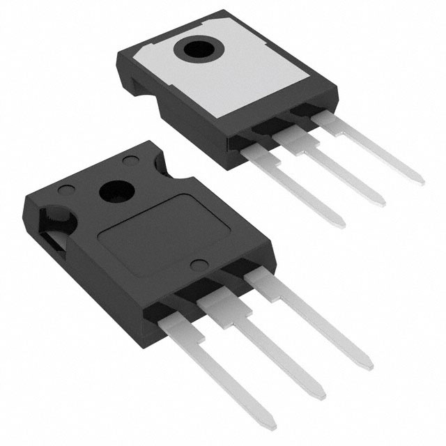
FCH104N60 N-Channel MOSFET 600V 37A Equivalent & Substitute Parts
Part Overview
The FCH104N60 is an N-Channel MOSFET manufactured by onsemi in the SuperFET® II series, rated for 600V drain-to-source voltage and 37A continuous drain current at 25°C. The device is housed in a TO-247-3 through-hole package and dissipates up to 357W at the case temperature. This part is classified as obsolete, necessitating identification of equivalent and substitute components for ongoing design support and production continuity. Substitute parts must maintain electrical compatibility across critical parameters including voltage rating, current capacity, on-resistance characteristics, and thermal performance while accommodating package variations where applicable.
Substiute Parts
Key Parameters
| Parameter | Value | Unit |
|---|---|---|
| Drain-to-Source Voltage (Vdss) | 600 | V |
| Continuous Drain Current (Id) @ 25°C | 37 | A (Tc) |
| On-Resistance (Rds On Max) @ Id, Vgs | 104 mOhm @ 18.5A, 10V | mOhm |
| Gate Threshold Voltage (Vgs(th) Max) @ Id | 3.5 | V @ 250µA |
| Gate Charge (Qg Max) @ Vgs | 82 | nC @ 10V |
| Power Dissipation (Max) | 357 | W (Tc) |
| Operating Temperature Range | -55 to 150 | °C (TJ) |
| Package Type | TO-247-3 | Through Hole |
| FET Type | N-Channel | |
| Technology | MOSFET (Metal Oxide) |
Substitute Part Grouping Explanation
Substitution eligibility for the FCH104N60 is determined by the following critical parameters:
Mandatory Compatibility Criteria:
- Drain-to-Source Voltage (Vdss): Minimum 600V (equal or higher rating required)
- Continuous Drain Current (Id): Minimum 37A at 25°C (equal or higher rating required)
- On-Resistance (Rds On): Maximum 104 mOhm at specified gate voltage (lower or equal values acceptable)
- Gate Threshold Voltage (Vgs(th)): Maximum 3.5V to 6.5V range (within device switching characteristics)
- Operating Temperature: -55°C to 150°C (matching or exceeding range)
- FET Type: N-Channel MOSFET technology only
- Package Compatibility: TO-247-3 primary; TO-264-3 and TO-264AA packages acceptable with mechanical verification
Substitution Groups:
Group 1 – Direct TO-247-3 Package Equivalents: Parts maintaining identical TO-247-3 packaging with comparable electrical ratings.
Group 2 – Higher Current Capacity Alternatives (TO-264 Package): Parts with increased current ratings (64A–82A) in larger TO-264-3 or TO-264AA packages, suitable for applications requiring thermal margin or higher current handling.
Group 3 – Lower Current Alternatives (TO-247-3 Package): Parts with reduced current ratings (26A–33A) in TO-247-3 packaging, applicable to current-limited applications.
Parameter Comparison
| Part Number | Manufacturer | Vdss (V) | Id @ 25°C (A) | Rds On Max (mOhm) | Vgs(th) Max (V) | Qg Max (nC) | Power Dissipation (W) | Package | Product Status |
|---|---|---|---|---|---|---|---|---|---|
| FCH104N60 | onsemi | 600 | 37 | 104 @ 18.5A, 10V | 3.5 | 82 @ 10V | 357 | TO-247-3 | Obsolete |
| NTHL099N60S5 | onsemi | 600 | 33 | 99 @ 13.5A, 10V | 4.0 | 48 @ 10V | 184 | TO-247-3 | Not For New Designs |
| IPW60R099CPFKSA1 | Infineon Technologies | 650 | 31 | 99 @ 18A, 10V | 3.5 | 80 @ 10V | 255 | TO-247-3 | Not For New Designs |
| IPW60R120P7XKSA1 | Infineon Technologies | 600 | 26 | 120 @ 8.2A, 10V | 4.0 | 36 @ 10V | 95 | TO-247-3 | Active |
| IXFB82N60P | IXYS | 600 | 82 | 75 @ 41A, 10V | 5.0 | 240 @ 10V | 1250 | TO-264-3, TO-264AA | Active |
| IXFB82N60Q3 | IXYS | 600 | 82 | 75 @ 41A, 10V | 6.5 | 275 @ 10V | 1560 | TO-264-3, TO-264AA | Active |
| IXFK64N60P | IXYS | 600 | 64 | 96 @ 500mA, 10V | 5.0 | 200 @ 10V | 1040 | TO-264-3, TO-264AA | Active |
| IXFK64N60P3 | IXYS | 600 | 64 | 95 @ 32A, 10V | 5.0 | 145 @ 10V | 1130 | TO-264-3, TO-264AA | Active |
| IXFK64N60Q3 | IXYS | 600 | 64 | 95 @ 32A, 10V | 6.5 | 190 @ 10V | 1250 | TO-264-3, TO-264AA | Active |
| IXFL82N60P | IXYS | 600 | 55 | 78 @ 41A, 10V | 5.0 | 240 @ 10V | 625 | TO-264-3, TO-264AA | Active |
| IXFR64N60Q3 | IXYS | 600 | 42 | 104 @ 32A, 10V | 6.5 | 190 @ 10V | 568 | TO-247-3 | Active |
Engineering Selection Recommendations
For Direct Replacement (TO-247-3 Package, Matching Current Rating):
IXFR64N60Q3 is the primary substitute for the FCH104N60 when package compatibility and current handling are critical. This part maintains the TO-247-3 form factor, exceeds the 37A continuous drain current requirement at 42A, and provides equivalent on-resistance performance at 104 mOhm. The device is in active production status with full RoHS3 compliance and REACH unaffected certification. Gate threshold voltage of 6.5V is within acceptable switching characteristics for standard gate drive circuits.
For Applications Requiring Reduced Current Capacity:
IPW60R120P7XKSA1 (Infineon CoolMOS™ P7 series) is suitable for current-limited applications requiring only 26A continuous drain current. This part maintains 600V Vdss rating, operates in TO-247-3 package, and is in active production status. Lower power dissipation (95W) and reduced gate charge (36 nC) provide advantages in low-power switching applications. RoHS3 compliance and REACH unaffected status confirmed.
For Applications Requiring Increased Current Capacity:
IXFK64N60P3 and IXFK64N60Q3 (IXYS HiPerFET™ series) provide 64A continuous drain current in TO-264AA package format. Both parts maintain 600V Vdss rating, deliver on-resistance of 95 mOhm, and are in active production. IXFK64N60P3 features lower gate charge (145 nC) compared to Q3 variant (190 nC), offering reduced switching losses. Mechanical package transition from TO-247-3 to TO-264AA requires PCB layout verification.
IXFL82N60P (IXYS HiPerFET™ Polar series) delivers 55A continuous drain current in ISOPLUS264™ package with superior on-resistance of 78 mOhm at 41A. This configuration provides thermal margin and reduced conduction losses for high-current applications. Active production status with full compliance certifications.
For Obsolete Part Replacement (onsemi SuperFET® Series):
NTHL099N60S5 (onsemi SuperFET® V series) maintains manufacturer continuity with 600V Vdss and TO-247-3 package. However, reduced current rating (33A) and lower power dissipation (184W) limit applicability to current-constrained designs. Product status is "Not For New Designs," restricting use to legacy system support only.
Compliance and Certification:
All recommended substitutes maintain RoHS3 compliance and REACH unaffected status, matching the original FCH104N60 environmental certifications. All parts operate across the -55°C to 150°C temperature range, ensuring thermal compatibility with existing thermal management designs.
Frequently Asked Questions (FAQ)
Q: Can NTHL099N60S5 directly replace FCH104N60 in existing designs?
A: NTHL099N60S5 shares identical TO-247-3 packaging and 600V voltage rating but delivers only 33A continuous drain current versus the FCH104N60's 37A specification. This 10.8% current reduction may exceed thermal or current-handling margins in designs optimized for 37A operation. Additionally, NTHL099N60S5 carries "Not For New Designs" status, limiting its use to legacy system maintenance only.
Q: What is the primary advantage of IXFR64N60Q3 as a substitute?
A: IXFR64N60Q3 maintains the TO-247-3 through-hole package format, eliminating PCB layout modifications. The part delivers 42A continuous drain current, exceeding the FCH104N60's 37A rating by 13.5%, providing thermal margin and design headroom. On-resistance of 104 mOhm matches the original specification exactly. Active production status ensures long-term availability and supply chain stability.
Q: Why do IXYS TO-264 package alternatives require PCB verification?
A: IXFK64N60P, IXFK64N60P3, IXFK64N60Q3, and IXFL82N60P employ TO-264-3 or TO-264AA package formats, which differ mechanically from the FCH104N60's TO-247-3 package. Pin spacing, lead geometry, and mounting hole patterns are not interchangeable. PCB layout redesign and thermal management verification are mandatory before implementation.
Q: Are all substitute parts RoHS3 compliant?
A: Yes. All substitute parts listed—NTHL099N60S5, IPW60R099CPFKSA1, IPW60R120P7XKSA1, IXFB82N60P, IXFB82N60Q3, IXFK64N60P, IXFK64N60P3, IXFK64N60Q3, IXFL82N60P, and IXFR64N60Q3—carry RoHS3 compliance certification. All are REACH unaffected, matching the environmental compliance profile of the original FCH104N60.
Q: What is the significance of gate threshold voltage differences between substitutes?
A: Gate threshold voltage (Vgs(th)) determines the gate voltage required to initiate channel conduction. The FCH104N60 specifies 3.5V maximum at 250µA. Substitute parts range from 3.5V (IPW60R099CPFKSA1) to 6.5V (IXFB82N60Q3, IXFK64N60Q3, IXFR64N60Q3). Higher threshold voltages require proportionally higher gate drive voltages to achieve full on-state conduction. Existing gate drive circuits must be evaluated to confirm compatibility with substitute threshold specifications.
Q: How does on-resistance affect thermal performance?
A: On-resistance (Rds On) directly determines conduction losses through the relationship P = I²R. Lower on-resistance reduces heat generation at equivalent current levels. The FCH104N60 specifies 104 mOhm at 18.5A, 10V. Substitutes range from 75 mOhm (IXFB82N60P, IXFB82N60Q3) to 120 mOhm (IPW60R120P7XKSA1). Lower on-resistance values reduce thermal load on heatsinks and improve overall system efficiency.
Q: Can IPW60R120P7XKSA1 be used in applications requiring 37A continuous current?
A: No. IPW60R120P7XKSA1 is rated for only 26A continuous drain current at 25°C, representing a 29.7% reduction from the FCH104N60's 37A specification. Operation above the rated current limit causes excessive junction temperature rise and accelerated device degradation. This part is suitable only for applications with current requirements of 26A or lower.
Q: What is the difference between IXFK64N60P and IXFK64N60P3?
A: Both parts deliver 64A continuous drain current and 600V Vdss in TO-264AA package. IXFK64N60P (Polar series) features 96 mOhm on-resistance at 500mA, 10V and 200 nC gate charge. IXFK64N60P3 (Polar3™ series) delivers 95 mOhm on-resistance at 32A, 10V and 145 nC gate charge. The P3 variant exhibits lower gate charge, reducing switching losses and gate drive power consumption. Both are in active production.
Q: Is package transition from TO-247-3 to TO-264AA feasible for retrofit applications?
A: Package transition is technically feasible but requires PCB redesign. TO-264AA packages feature different pin spacing and lead configurations than TO-247-3. Existing PCB footprints cannot accommodate TO-264AA devices without layout modification. Thermal management design must also be re-evaluated, as TO-264AA packages offer different thermal coupling characteristics to heatsinks. Retrofit applications should prioritize TO-247-3 alternatives such as IXFR64N60Q3 to minimize design changes.
Q: What is the operating temperature range for all substitute parts?
A: All substitute parts operate across the -55°C to 150°C junction temperature range, matching the FCH104N60 specification. This ensures thermal compatibility with existing thermal management designs and operating environment specifications.
Alternative Parts

SJ6012L2TP
Littelfuse Inc.
6 Alternative Parts

JMK107BBJ476MA-RE
Taiyo Yuden
10 Alternative Parts

GMK107BBJ475MA-T
Taiyo Yuden
5 Alternative Parts
SJ6020N2ARP
Littelfuse Inc.
3 Alternative Parts
SJ6025R2ATP
Littelfuse Inc.
4 Alternative Parts

2474-05L
API Delevan Inc.
1 Alternative Parts

4590R-684K
API Delevan Inc.
1 Alternative Parts

CM6560R-334
API Delevan Inc.
1 Alternative Parts

CM6460-104
API Delevan Inc.
1 Alternative Parts

5526-12
API Delevan Inc.
1 Alternative Parts