


Request Quote
(Ships tomorrow)
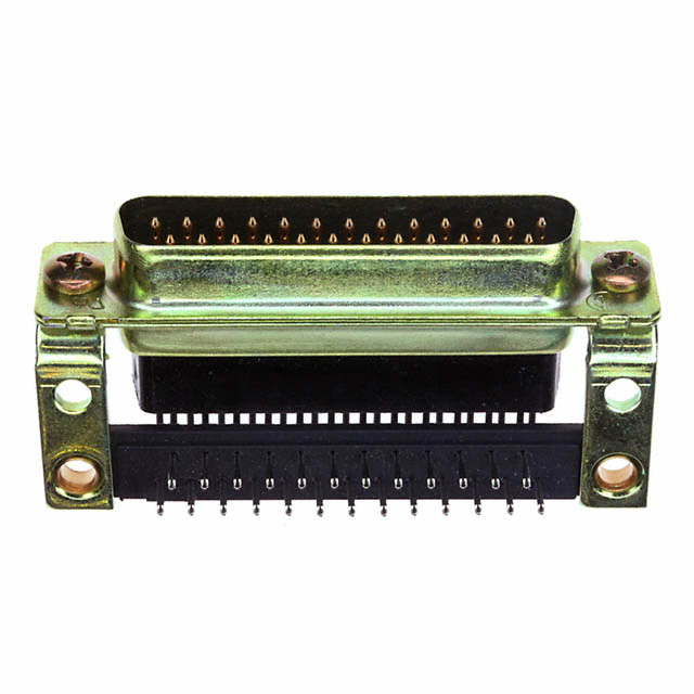
FCE17B25PC2EB D-Sub 25 Position Right Angle Solder Plug Connector
Part Overview
The FCE17B25PC2EB is a 25 position D-Sub plug connector manufactured by Amphenol ICC (Commercial Products). This connector features male pins, right angle mounting orientation, and solder termination. The part is currently active in production with 1146 units in stock. D-Sub connectors of this configuration are essential components in applications requiring standardized signal distribution across multiple channels with reliable mechanical and electrical interfaces. Equivalent and substitute parts are identified to support procurement flexibility, inventory management, and supply chain continuity.
Substiute Parts
Key Parameters
| Parameter | Value |
|---|---|
| Connector Style | D-Sub |
| Connector Type | Plug, Male Pins |
| Number of Positions | 25 |
| Number of Rows | 2 |
| Shell Size, Connector Layout | 3 (DB, B) |
| Mounting Type | Through Hole, Right Angle |
| Termination | Solder |
| Current Rating (Amps) | 5A |
| Operating Temperature | -40°C ~ 85°C |
| Material Flammability Rating | UL94 V-0 |
| RoHS Status | RoHS Compliant |
Substitute Part Grouping Explanation
Substitution eligibility for the FCE17B25PC2EB is determined by the following critical parameters:
Core Compatibility Requirements:
- Connector Style: D-Sub
- Connector Type: Plug, Male Pins
- Number of Positions: 25
- Number of Rows: 2
- Shell Size, Connector Layout: 3 (DB, B)
- Mounting Type: Through Hole, Right Angle
- Termination: Solder
- Material Flammability Rating: UL94 V-0
Allowable Variations:
- Current Rating: 5A or higher
- Operating Temperature: Range must encompass or exceed -40°C ~ 85°C
- Shell Material Finish: Steel with various plating options (Tin, Nickel, Chromate)
- Contact Finish: Gold (standard across all parts)
- Flange Feature: Unthreaded housing, threaded housing (4-40), or screwlock configurations
- Features: Variations in grounding indents, board lock, ground strap, and mounting brackets
- RoHS Status: RoHS Compliant or ROHS3 Compliant acceptable
Seven substitute parts meet these criteria across three manufacturers: NorComp Inc. (four variants), TE Connectivity AMP Connectors (three variants).
Parameter Comparison
| Parameter | FCE17B25PC2EB (Amphenol ICC) | 183-025-113R161 (NorComp) | 183-025-113R171 (NorComp) | 183-025-113R181 (NorComp) | 183-025-113R531 (NorComp) | 183-025-113R561 (NorComp) | 205857-1 (TE Connectivity) | 5205857-1 (TE Connectivity) | 5747022-2 (TE Connectivity) |
|---|---|---|---|---|---|---|---|---|---|
| Connector Style | D-Sub | D-Sub | D-Sub | D-Sub | D-Sub | D-Sub | D-Sub | D-Sub | D-Sub |
| Connector Type | Plug, Male Pins | Plug, Male Pins | Plug, Male Pins | Plug, Male Pins | Plug, Male Pins | Plug, Male Pins | Plug, Male Pins | Plug, Male Pins | Plug, Male Pins |
| Number of Positions | 25 | 25 | 25 | 25 | 25 | 25 | 25 | 25 | 25 |
| Number of Rows | 2 | 2 | 2 | 2 | 2 | 2 | 2 | 2 | 2 |
| Shell Size, Connector Layout | 3 (DB, B) | 3 (DB, B) | 3 (DB, B) | 3 (DB, B) | 3 (DB, B) | 3 (DB, B) | 3 (DB, B) | 3 (DB, B) | 3 (DB, B) |
| Mounting Type | Through Hole, Right Angle | Panel Mount, Through Hole, Right Angle | Panel Mount, Through Hole, Right Angle | Panel Mount, Through Hole, Right Angle | Panel Mount, Through Hole, Right Angle | Panel Mount, Through Hole, Right Angle | Through Hole, Right Angle | Through Hole, Right Angle | Through Hole, Right Angle |
| Termination | Solder | Solder | Solder | Solder | Solder | Solder | Solder | Solder | Solder |
| Shell Material, Finish | Steel, Tin Plated | Steel, Nickel Plated | Steel, Nickel Plated | Steel, Nickel Plated | Steel, Nickel Plated | Steel, Nickel Plated | Steel, Yellow Chromate Plated Zinc | Steel, Yellow Chromate Plated Zinc | Steel, Tin Plated |
| Contact Finish | Gold | Gold | Gold | Gold | Gold | Gold | Gold | Gold | Gold |
| Current Rating (Amps) | 5A | 5A | 5A | 5A | 5A | 5A | 6A | 6A | 6A |
| Operating Temperature | -40°C ~ 85°C | -55°C ~ 105°C | -55°C ~ 105°C | -55°C ~ 105°C | -55°C ~ 105°C | -55°C ~ 105°C | -55°C ~ 105°C | -55°C ~ 105°C | -55°C ~ 105°C |
| Material Flammability Rating | UL94 V-0 | UL94 V-0 | UL94 V-0 | UL94 V-0 | UL94 V-0 | UL94 V-0 | UL94 V-0 | UL94 V-0 | UL94 V-0 |
| Flange Feature | Housing/Shell (Unthreaded) | Housing/Shell (Unthreaded) | Housing/Shell (4-40) | Mating Side, Female Screwlock (4-40) | Housing/Shell (4-40) | Mating Side, Female Screwlock (4-40) | Mating Side, Standard Screws (4-40) | Mating Side, Standard Screws (4-40) | Mating Side, Female Screwlock (4-40) |
| RoHS Status | RoHS Compliant | ROHS3 Compliant | ROHS3 Compliant | ROHS3 Compliant | ROHS3 Compliant | ROHS3 Compliant | RoHS non-compliant | ROHS3 Compliant | ROHS3 Compliant |
Engineering Selection Recommendations
Primary Substitutes (Recommended for Direct Replacement):
The NorComp Inc. 183 series connectors (183-025-113R161, 183-025-113R171, 183-025-113R181, 183-025-113R531, 183-025-113R561) are fully qualified substitutes. All five variants are ROHS3 Compliant, matching or exceeding the RoHS compliance status of the FCE17B25PC2EB. These parts feature expanded operating temperature ranges (-55°C ~ 105°C) and equivalent current ratings (5A). Inventory availability ranges from 1140 to 2139 units. Selection among these five variants depends on specific flange feature requirements:
- 183-025-113R161: Unthreaded housing flange, ground strap feature
- 183-025-113R171: Threaded housing (4-40), ground strap feature
- 183-025-113R181: Female screwlock (4-40) mating side, ground strap feature
- 183-025-113R531: Threaded housing (4-40), board lock feature
- 183-025-113R561: Female screwlock (4-40) mating side, board lock feature
Secondary Substitutes (Conditional Use):
TE Connectivity AMP Connectors 5205857-1 and 5747022-2 are qualified substitutes with ROHS3 Compliance status. Both parts feature 6A current ratings (exceeding the 5A requirement) and expanded operating temperature ranges. The 5205857-1 (AMPLIMITE HDP-20 series) provides mating side standard screws (4-40) configuration. The 5747022-2 (AMPLIMITE HD-20 series) provides mating side female screwlock (4-40) configuration with grounding indents and mounting brackets.
Non-Recommended Substitute:
The TE Connectivity 205857-1 is RoHS non-compliant and REACH Affected. This part does not meet current regulatory compliance requirements for new designs and should not be selected for applications requiring RoHS compliance certification.
Frequently Asked Questions (FAQ)
Q: What are the critical parameters that determine if a part can substitute for the FCE17B25PC2EB?
A: The following parameters must match exactly: D-Sub connector style, plug with male pins, 25 positions in 2 rows, shell size 3 (DB, B), through hole right angle mounting, and solder termination. All substitute parts must maintain UL94 V-0 flammability rating. Current rating must be 5A or higher, and operating temperature range must encompass or exceed -40°C to 85°C.
Q: Can I use a substitute part with a higher current rating?
A: Yes. The substitute parts with 6A current ratings (205857-1, 5205857-1, 5747022-2) are electrically compatible with applications designed for 5A connectors. Higher current ratings provide additional design margin and do not create compatibility issues.
Q: What is the difference between the various NorComp 183 series variants?
A: The five NorComp variants differ in flange feature configuration and mechanical features. The 183-025-113R161 has an unthreaded housing flange. The 183-025-113R171 and 183-025-113R531 have threaded housing (4-40). The 183-025-113R181 and 183-025-113R561 have female screwlock (4-40) on the mating side. Additionally, 183-025-113R531 and 183-025-113R561 include board lock features, while 183-025-113R161, 183-025-113R171, and 183-025-113R181 include ground strap features.
Q: Does RoHS compliance status affect substitution eligibility?
A: For new designs and applications subject to RoHS regulations, substitute parts must be RoHS Compliant or ROHS3 Compliant. The FCE17B25PC2EB is RoHS Compliant. All recommended substitutes (NorComp 183 series and TE Connectivity 5205857-1, 5747022-2) are ROHS3 Compliant, which is acceptable. The TE Connectivity 205857-1 is RoHS non-compliant and should not be used in regulated applications.
Q: What packaging formats are available for substitute parts?
A: The FCE17B25PC2EB is supplied in Box packaging. NorComp 183 series substitutes are supplied in Tray packaging. TE Connectivity substitutes (205857-1, 5205857-1, 5747022-2) are supplied in Bulk packaging. Packaging format does not affect electrical or mechanical compatibility but may impact receiving, storage, and handling procedures.
Q: Are there temperature rating differences between the main part and substitutes?
A: Yes. The FCE17B25PC2EB operates from -40°C to 85°C. All substitute parts operate from -55°C to 105°C, providing extended temperature range capability. This expanded range is compatible with applications designed for the original part's temperature specification.
Q: Can I interchange parts with different shell material finishes?
A: Yes. The FCE17B25PC2EB features tin plated steel shell. Substitute parts feature nickel plated or yellow chromate plated zinc shells. All finishes provide equivalent corrosion resistance and electrical performance for standard applications. Material finish selection may be driven by specific environmental or compatibility requirements in your application.
Q: What is the significance of the backset spacing parameter?
A: Backset spacing defines the distance from the connector mounting face to the contact insertion point. The FCE17B25PC2EB specifies 0.590" (14.99mm). NorComp substitutes maintain this identical spacing. TE Connectivity substitutes specify 0.545" (13.84mm), which is a minor variation. This difference may affect PCB layout and mechanical clearance in space-constrained applications.
Alternative Parts

SJ6012L2TP
Littelfuse Inc.
6 Alternative Parts

JMK107BBJ476MA-RE
Taiyo Yuden
10 Alternative Parts

GMK107BBJ475MA-T
Taiyo Yuden
5 Alternative Parts
SJ6020N2ARP
Littelfuse Inc.
3 Alternative Parts
SJ6025R2ATP
Littelfuse Inc.
4 Alternative Parts

2474-05L
API Delevan Inc.
1 Alternative Parts

4590R-684K
API Delevan Inc.
1 Alternative Parts

CM6560R-334
API Delevan Inc.
1 Alternative Parts

CM6460-104
API Delevan Inc.
1 Alternative Parts

5526-12
API Delevan Inc.
1 Alternative Parts