


Request Quote
(Ships tomorrow)
Equivalent & Substitute Parts for ELL-ATV151M
Part Overview
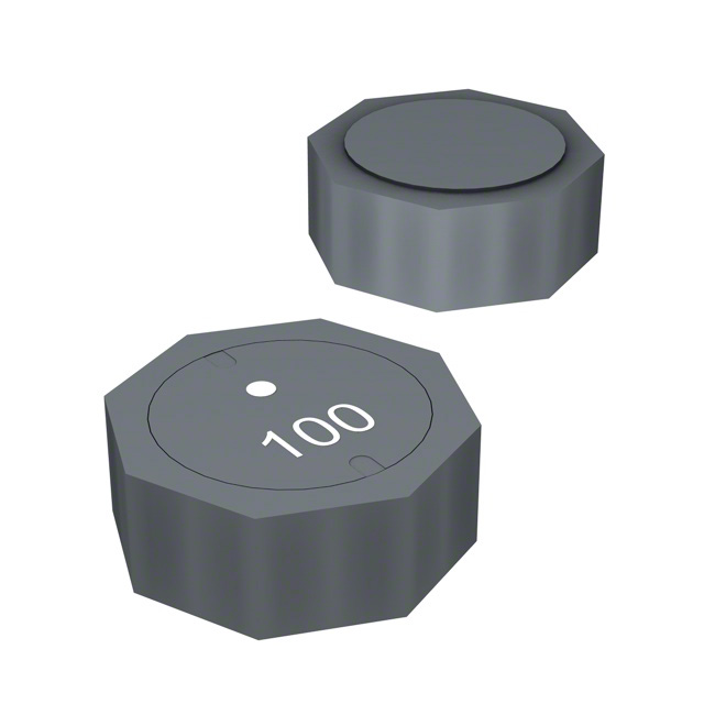
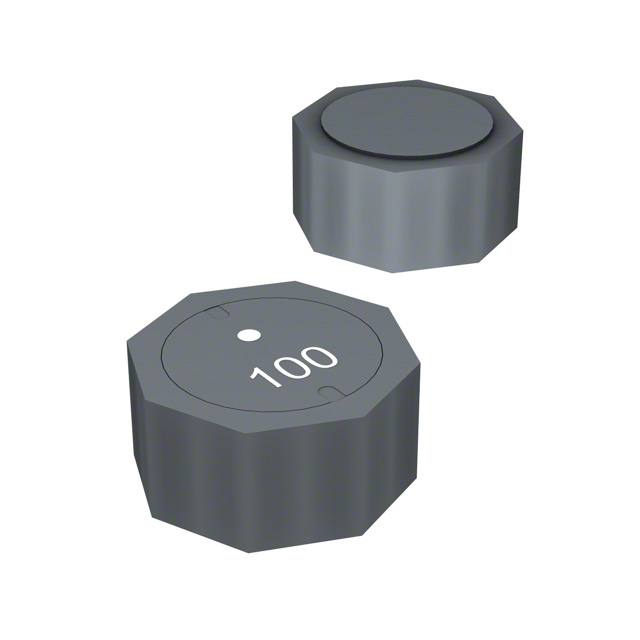
The Panasonic ELL-ATV151M is a 150 µH shielded drum core wirewound inductor rated for 780 mA with 250mOhm DC resistance, designed for surface mount applications in a 10.00mm x 10.00mm footprint. This part is classified as obsolete, necessitating identification of active equivalent components that maintain functional compatibility within specified electrical and mechanical parameters.
Substiute Parts
Key Parameters
| Parameter | Value |
|---|---|
| Inductance | 150 µH |
| Current Rating | 780 mA |
| DC Resistance (DCR) | 250mOhm |
| Shielding | Shielded |
| Core Material | Ferrite |
| Mounting Type | Surface Mount |
| Package Footprint | 10.00mm x 10.00mm |
| Height (Max) | 4.50mm |
| RoHS Status | ROHS3 Compliant |
Substitute Part Grouping Explanation
Substitution eligibility for the ELL-ATV151M is determined by the following criteria:
Primary Matching Parameters:
- Inductance value: 150 µH (exact match required)
- Core material: Ferrite drum core wirewound construction
- Mounting type: Surface mount
- Package footprint: 10.00mm x 10.00mm
- Compliance: ROHS3 compliant
Secondary Compatibility Parameters:
- Current rating: Must equal or exceed 780 mA
- DC resistance: Acceptable range determined by circuit design tolerance
- Shielding configuration: Shielded preferred for EMI-sensitive applications; unshielded acceptable if circuit design permits
- Height: Physical clearance constraints may limit acceptable maximum seated height
The three identified substitute parts meet the primary matching criteria and represent active products with enhanced or equivalent electrical performance characteristics.
Parameter Comparison
| Parameter | ELL-ATV151M (Main) | SRU1038-151Y | SRU1048-151Y | SDR1045-151K |
|---|---|---|---|---|
| Manufacturer | Panasonic | Bourns Inc. | Bourns Inc. | Bourns Inc. |
| Product Status | Obsolete | Active | Active | Active |
| Inductance | 150 µH | 150 µH | 150 µH | 150 µH |
| Tolerance | ±20% | ±30% | ±30% | ±10% |
| Current Rating | 780 mA | 900 mA | 1 A | 850 mA |
| DC Resistance (DCR) | 250mOhm | 358mOhm | 235mOhm | 700mOhm Max |
| Shielding | Shielded | Shielded | Shielded | Unshielded |
| Core Material | Ferrite | Ferrite | Ferrite | Ferrite |
| Mounting Type | Surface Mount | Surface Mount | Surface Mount | Surface Mount |
| Footprint | 10.00mm x 10.00mm | 10.00mm x 10.00mm | 10.00mm x 10.00mm | 10.00mm x 10.00mm |
| Height (Max) | 4.50mm | 4.10mm | 5.10mm | 4.80mm |
| Operating Temperature | Not specified | -40°C ~ 125°C | -40°C ~ 125°C | -40°C ~ 125°C |
| RoHS Status | ROHS3 Compliant | ROHS3 Compliant | ROHS3 Compliant | ROHS3 Compliant |
| Packaging | Not specified | Tape & Reel (TR) | Tape & Reel (TR) | Tape & Reel (TR) |
Engineering Selection Recommendations
SRU1048-151Y (Primary Substitute) This Bourns shielded inductor provides the lowest DC resistance (235mOhm) among active alternatives, exceeding the original current rating at 1 A. Active product status ensures long-term availability and supply chain continuity. Height of 5.10mm requires verification against PCB clearance constraints. Shielded configuration maintains EMI performance equivalent to the original design.
SRU1038-151Y (Secondary Substitute) This Bourns shielded inductor offers moderate DC resistance (358mOhm) with 900 mA current rating and the lowest profile height (4.10mm) among substitutes. Active product status and shielded construction provide direct functional equivalence. Suitable for space-constrained applications where height is a critical design parameter.
SDR1045-151K (Alternative for Unshielded Applications) This Bourns unshielded inductor provides the highest current rating (850 mA) and lowest inductance tolerance (±10%). Unshielded configuration results in higher DC resistance (700mOhm Max), making this option suitable only for applications where EMI shielding is not required and higher resistance is acceptable. Active product status and tape & reel packaging support production environments.
All three substitutes are ROHS3 compliant with unlimited moisture sensitivity level (MSL 1), matching the original part's environmental compliance profile.
Frequently Asked Questions (FAQ)
Q: Can SRU1048-151Y directly replace ELL-ATV151M without circuit modification? A: SRU1048-151Y meets all primary electrical and mechanical matching criteria: 150 µH inductance, ferrite drum core, shielded construction, surface mount configuration, and 10.00mm x 10.00mm footprint. The 235mOhm DC resistance is lower than the original 250mOhm, and the 1 A current rating exceeds the 780 mA requirement. Physical height of 5.10mm must be verified against PCB clearance. No circuit modification is required if height constraints are satisfied.
Q: What is the impact of higher DC resistance in SDR1045-151K? A: The SDR1045-151K exhibits 700mOhm maximum DC resistance compared to the original 250mOhm. This 2.8x increase results in higher power dissipation and voltage drop across the inductor. This substitute is suitable only for applications where EMI shielding is not a design requirement and where the higher resistance does not compromise circuit performance or thermal management.
Q: Are all substitute parts available in tape & reel packaging? A: Yes. SRU1038-151Y, SRU1048-151Y, and SDR1045-151K are all supplied in tape & reel (TR) packaging, supporting automated assembly processes. Original inventory levels are confirmed as available from authorized distributors.
Q: How do inductance tolerances affect circuit performance? A: The original ELL-ATV151M specifies ±20% tolerance. SRU1038-151Y and SRU1048-151Y specify ±30% tolerance, while SDR1045-151K specifies ±10% tolerance. Wider tolerances may impact frequency response and filtering characteristics in precision applications. Circuit design should account for the specified tolerance range of the selected substitute.
Q: What is the difference between shielded and unshielded configurations? A: Shielded inductors (SRU1038-151Y, SRU1048-151Y, ELL-ATV151M) contain ferrite shielding to contain magnetic fields and reduce electromagnetic interference with adjacent components. Unshielded inductors (SDR1045-151K) allow magnetic field radiation, resulting in lower DC resistance but potential EMI coupling. Selection depends on circuit layout and EMI sensitivity requirements.
Q: Can height differences affect PCB assembly? A: Yes. The original ELL-ATV151M has a maximum seated height of 4.50mm. SRU1038-151Y (4.10mm) provides additional clearance, while SRU1048-151Y (5.10mm) and SDR1045-151K (4.80mm) require verification against component stacking, solder joint clearance, and conformal coating processes. Height differences may necessitate PCB layout adjustments or assembly process validation.
Alternative Parts

SJ6012L2TP
Littelfuse Inc.
6 Alternative Parts

JMK107BBJ476MA-RE
Taiyo Yuden
10 Alternative Parts

GMK107BBJ475MA-T
Taiyo Yuden
5 Alternative Parts
SJ6020N2ARP
Littelfuse Inc.
3 Alternative Parts
SJ6025R2ATP
Littelfuse Inc.
4 Alternative Parts

2474-05L
API Delevan Inc.
1 Alternative Parts

4590R-684K
API Delevan Inc.
1 Alternative Parts

CM6560R-334
API Delevan Inc.
1 Alternative Parts

CM6460-104
API Delevan Inc.
1 Alternative Parts

5526-12
API Delevan Inc.
1 Alternative Parts