


Request Quote
(Ships tomorrow)
ELL-ATV101M Equivalent & Substitute Parts
Part Overview
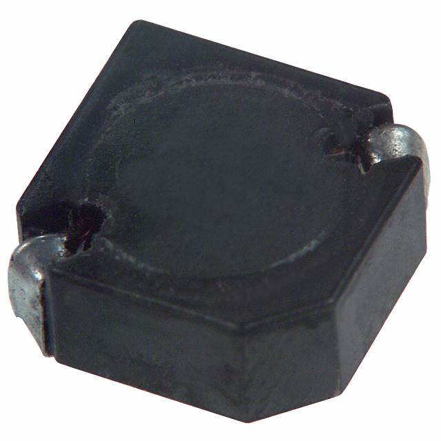
The Panasonic ELL-ATV101M is a 100 µH shielded drum core wirewound inductor rated for 1 A with 180 mOhm DC resistance. This component is classified as obsolete, making substitute parts necessary for new designs and ongoing production support. The part is ROHS3 compliant with unlimited moisture sensitivity rating (MSL 1).
Substiute Parts
Key Parameters
| Parameter | Value |
|---|---|
| Inductance | 100 µH |
| Tolerance | ±20% |
| Current Rating | 1 A |
| DC Resistance (DCR) | 180 mOhm |
| Shielding | Shielded |
| Core Material | Ferrite |
| Mounting Type | Surface Mount |
| Size | 10.00 mm x 10.00 mm |
| Height (Max) | 4.50 mm |
| RoHS Status | ROHS3 Compliant |
Substitute Part Grouping Explanation
Substitution for the ELL-ATV101M is determined by the following critical parameters:
- Inductance Value: 100 µH (fixed requirement)
- Current Rating: Minimum 1 A (equal or higher acceptable)
- DC Resistance: Baseline 180 mOhm (higher values acceptable within application limits)
- Shielding Type: Shielded (electromagnetic interference containment)
- Core Material: Ferrite (magnetic performance consistency)
- Mounting Type: Surface Mount (PCB compatibility)
- Package Dimensions: 10.00 mm x 10.00 mm footprint (physical fit)
- RoHS Compliance: ROHS3 Compliant (regulatory requirement)
Substitute parts must meet or exceed the current rating and maintain shielded construction. Tolerance variations and DCR increases are acceptable provided the application thermal and performance margins accommodate them.
Parameter Comparison
| Parameter | ELL-ATV101M | B82464G4104M000 | B82464P4104M000 | SDR1045-101K | SLF10145T-101M1R0-PF | SRU1038-101Y |
|---|---|---|---|---|---|---|
| Manufacturer | Panasonic | EPCOS - TDK | EPCOS - TDK | Bourns Inc. | TDK Corporation | Bourns Inc. |
| Inductance | 100 µH | 100 µH | 100 µH | 100 µH | 100 µH | 100 µH |
| Tolerance | ±20% | ±20% | ±20% | ±10% | ±20% | ±30% |
| Current Rating (A) | 1 | 1.05 | 1.05 | 1.1 | 1.1 | 1.3 |
| DC Resistance (mOhm) | 180 | 220 Max | 220 Max | 540 Max | 240 Max | 220 |
| Shielding | Shielded | Shielded | Shielded | Unshielded | Shielded | Shielded |
| Core Material | Ferrite | Ferrite | Ferrite | Ferrite | Ferrite | Ferrite |
| Mounting Type | Surface Mount | Surface Mount | Surface Mount | Surface Mount | Surface Mount | Surface Mount |
| Size (mm) | 10.00 x 10.00 | 10.40 x 10.40 | 10.40 x 10.40 | 10.00 x 10.00 | 10.10 x 10.10 | 10.00 x 10.00 |
| Height Max (mm) | 4.50 | 4.80 | 4.80 | 4.80 | 4.80 | 4.10 |
| Product Status | Obsolete | Active | Active | Active | Not For New Designs | Active |
| RoHS Status | ROHS3 Compliant | ROHS3 Compliant | ROHS3 Compliant | ROHS3 Compliant | ROHS3 Compliant | ROHS3 Compliant |
| Operating Temperature | Not specified | -55°C ~ 150°C | -55°C ~ 150°C | -40°C ~ 125°C | -40°C ~ 105°C | -40°C ~ 125°C |
Engineering Selection Recommendations
Primary Substitutes (Active Status, Shielded Construction)
B82464G4104M000 and B82464P4104M000 from EPCOS - TDK Electronics are the preferred substitutes. Both are active products with AEC-Q200 automotive qualification, higher current ratings (1.05 A), and extended operating temperature range (-55°C to 150°C). The slightly increased DCR (220 mOhm max) and package dimensions (10.40 x 10.40 mm) require PCB layout verification for footprint compatibility.
SRU1038-101Y from Bourns Inc. is an active alternative with the highest current rating (1.3 A) and identical footprint dimensions (10.00 x 10.00 mm) to the original part. The lower profile height (4.10 mm) provides additional design flexibility. The ±30% tolerance is wider than the original specification.
Secondary Substitute (Not For New Designs)
SLF10145T-101M1R0-PF from TDK Corporation is classified as "Not For New Designs" and should be used only for legacy system support or repair applications. It maintains shielded construction and meets current requirements but has a restricted product lifecycle status.
Not Recommended
SDR1045-101K from Bourns Inc. is an unshielded inductor. While it meets inductance and current specifications, the absence of shielding makes it unsuitable as a direct substitute for the shielded ELL-ATV101M in applications requiring electromagnetic containment.
Frequently Asked Questions (FAQ)
Q: Can SDR1045-101K replace the ELL-ATV101M?
A: No. The SDR1045-101K is an unshielded inductor, while the ELL-ATV101M is shielded. Shielding provides electromagnetic interference containment. Substitution is only valid if the application does not require shielded construction.
Q: Are the B82464G4104M000 and B82464P4104M000 interchangeable?
A: Both parts have identical electrical specifications (100 µH, 1.05 A, 220 mOhm max DCR, shielded). The primary difference is packaging: B82464G4104M000 uses Tape & Reel, while B82464P4104M000 also uses Tape & Reel. Both are suitable substitutes with equivalent performance.
Q: Will the larger package dimensions of B82464 series parts fit my PCB?
A: The B82464 series measures 10.40 x 10.40 mm compared to the original 10.00 x 10.00 mm. PCB layout verification is required to confirm footprint compatibility. The increased height (4.80 mm vs. 4.50 mm) must also be checked against clearance constraints.
Q: What is the impact of higher DC resistance in substitute parts?
A: Substitute parts have DCR values ranging from 220 mOhm to 540 mOhm compared to the original 180 mOhm. Higher DCR increases power dissipation and heat generation. Thermal analysis is required to confirm the application can tolerate the increased losses without exceeding temperature limits.
Q: Is SRU1038-101Y suitable for new designs?
A: Yes. SRU1038-101Y is an active product from Bourns Inc. with no lifecycle restrictions. It provides higher current capacity (1.3 A) and maintains the original footprint dimensions (10.00 x 10.00 mm), making it a direct mechanical fit.
Q: Why is SLF10145T-101M1R0-PF marked "Not For New Designs"?
A: This designation indicates the product is in end-of-life status. While available for existing applications, TDK does not recommend its use in new product development. Use only for legacy system support or repair.
Alternative Parts

SJ6012L2TP
Littelfuse Inc.
6 Alternative Parts

JMK107BBJ476MA-RE
Taiyo Yuden
10 Alternative Parts

GMK107BBJ475MA-T
Taiyo Yuden
5 Alternative Parts
SJ6020N2ARP
Littelfuse Inc.
3 Alternative Parts
SJ6025R2ATP
Littelfuse Inc.
4 Alternative Parts

2474-05L
API Delevan Inc.
1 Alternative Parts

4590R-684K
API Delevan Inc.
1 Alternative Parts

CM6560R-334
API Delevan Inc.
1 Alternative Parts

CM6460-104
API Delevan Inc.
1 Alternative Parts

5526-12
API Delevan Inc.
1 Alternative Parts