


Request Quote
(Ships tomorrow)
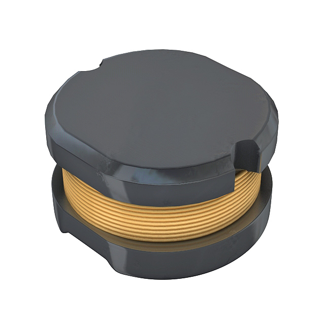
ELC-3FN150M Equivalent & Substitute Parts
Part Overview
The ELC-3FN150M is a 15 µH unshielded surface mount inductor manufactured by Panasonic Electronic Components, rated for 370 mA with 1Ohm DC resistance. This component is classified as obsolete, making identification of functionally equivalent alternatives essential for ongoing design support and production continuity. Substitute parts must maintain the core electrical specifications—inductance value, current rating, and DC resistance—while accommodating minor variations in package dimensions and performance characteristics.
Substiute Parts
Key Parameters
| Parameter | Value |
|---|---|
| Inductance | 15 µH |
| Tolerance | ±20% |
| Current Rating | 370 mA |
| DC Resistance (DCR) | 1Ohm |
| Shielding | Unshielded |
| Mounting Type | Surface Mount |
| Package Type | Nonstandard |
| Size | 3.20mm x 3.20mm x 1.20mm (max height) |
| RoHS Status | RoHS Compliant |
| MSL Rating | 1 (Unlimited) |
Substitute Part Grouping Explanation
Substitution eligibility for the ELC-3FN150M is determined by the following critical parameters:
- Inductance Value: Must be 15 µH with ±20% tolerance to maintain circuit performance
- Current Rating: Substitute must support minimum 370 mA; higher ratings provide design margin
- DC Resistance: Substitute DCR must not exceed 1Ohm to prevent excessive power dissipation
- Mounting Type: Surface mount configuration required for PCB compatibility
- Shielding Configuration: Unshielded topology must be preserved
- Environmental Compliance: RoHS compliance and MSL rating must meet or exceed original specifications
The SDR0302-150ML from Bourns Inc. qualifies as a direct substitute based on matching inductance, tolerance, shielding, and mounting type. The substitute exhibits superior current handling (650 mA vs. 370 mA) and lower DC resistance (400mOhm vs. 1Ohm), providing enhanced performance margins. Minor dimensional variations fall within acceptable PCB layout tolerances for nonstandard packages.
Parameter Comparison
| Parameter | ELC-3FN150M (Panasonic) | SDR0302-150ML (Bourns) | Compatibility |
|---|---|---|---|
| Inductance | 15 µH | 15 µH | Match |
| Tolerance | ±20% | ±20% | Match |
| Current Rating (Amps) | 370 mA | 650 mA | Substitute exceeds requirement |
| DC Resistance (DCR) | 1Ohm | 400mOhm Max | Substitute superior |
| Shielding | Unshielded | Unshielded | Match |
| Mounting Type | Surface Mount | Surface Mount | Match |
| Package Type | Nonstandard | Nonstandard | Match |
| Size (L x W) | 3.20mm x 3.20mm | 3.00mm x 2.80mm | Dimensionally compatible |
| Height (Max) | 1.20mm | 2.80mm | Substitute taller; verify clearance |
| RoHS Status | RoHS Compliant | ROHS3 Compliant | Both compliant |
| MSL Rating | 1 (Unlimited) | 1 (Unlimited) | Match |
| Product Status | Obsolete | Active | Substitute actively manufactured |
Engineering Selection Recommendations
The SDR0302-150ML is the qualified substitute for the obsolete ELC-3FN150M based on the following engineering criteria:
Electrical Compatibility: Both components maintain 15 µH inductance with ±20% tolerance and unshielded configuration. The substitute's 650 mA current rating and 400mOhm DCR exceed the original 370 mA / 1Ohm specification, reducing thermal stress and improving reliability margins.
Compliance Status: The SDR0302-150ML holds ROHS3 Compliant certification, meeting current regulatory requirements. Both components carry MSL 1 (Unlimited) moisture sensitivity ratings, ensuring equivalent handling and storage protocols.
Manufacturing Status: The substitute is actively manufactured by Bourns Inc., ensuring long-term availability and supply chain stability compared to the obsolete Panasonic component.
Physical Considerations: The substitute's footprint (3.00mm x 2.80mm) is slightly smaller than the original (3.20mm x 3.20mm), but the increased height (2.80mm vs. 1.20mm) requires verification of vertical clearance in the target PCB assembly. Dimensional compatibility must be confirmed during design integration.
Frequently Asked Questions (FAQ)
Q: Can the SDR0302-150ML directly replace the ELC-3FN150M without circuit modification?
A: Yes, from an electrical standpoint. Both components share identical inductance (15 µH), tolerance (±20%), and shielding configuration. The substitute's superior current rating and lower DC resistance provide performance enhancement without circuit redesign. Physical PCB layout must be verified due to height difference.
Q: What is the significance of the current rating difference (370 mA vs. 650 mA)?
A: The substitute's higher current rating indicates greater saturation margin and reduced thermal dissipation at the original operating point. This improves component longevity and reliability. No circuit modification is required; the substitute simply operates with greater design margin.
Q: How does the DC resistance difference (1Ohm vs. 400mOhm) affect circuit performance?
A: Lower DC resistance reduces I²R power loss. At 370 mA operation, the original component dissipates approximately 137 mW, while the substitute dissipates approximately 55 mW. This reduction improves thermal performance and efficiency, particularly in power-sensitive applications.
Q: Are there packaging or handling differences between these components?
A: Both components carry MSL 1 (Unlimited) ratings, requiring identical moisture control protocols. The substitute is supplied in Tape & Reel packaging (standard for active production), while the original may have different packaging due to obsolescence. Storage and reflow conditions remain equivalent.
Q: What is the primary reason for substitution?
A: The ELC-3FN150M is obsolete and no longer manufactured by Panasonic. The SDR0302-150ML provides functional equivalence with active manufacturing status, ensuring design continuity and supply chain reliability for new production and field service applications.
Q: Must PCB layout be modified for the substitute?
A: The footprint difference (3.20mm x 3.20mm to 3.00mm x 2.80mm) is minor and typically accommodated within standard PCB tolerances. However, the height increase (1.20mm to 2.80mm) requires clearance verification to prevent interference with adjacent components or enclosure constraints. Confirm vertical spacing before implementation.
Alternative Parts

SJ6012L2TP
Littelfuse Inc.
6 Alternative Parts

JMK107BBJ476MA-RE
Taiyo Yuden
10 Alternative Parts

GMK107BBJ475MA-T
Taiyo Yuden
5 Alternative Parts
SJ6020N2ARP
Littelfuse Inc.
3 Alternative Parts
SJ6025R2ATP
Littelfuse Inc.
4 Alternative Parts

2474-05L
API Delevan Inc.
1 Alternative Parts

4590R-684K
API Delevan Inc.
1 Alternative Parts

CM6560R-334
API Delevan Inc.
1 Alternative Parts

CM6460-104
API Delevan Inc.
1 Alternative Parts

5526-12
API Delevan Inc.
1 Alternative Parts