


Request Quote
(Ships tomorrow)
ELC-18E151L Equivalent & Substitute Parts
Part Overview
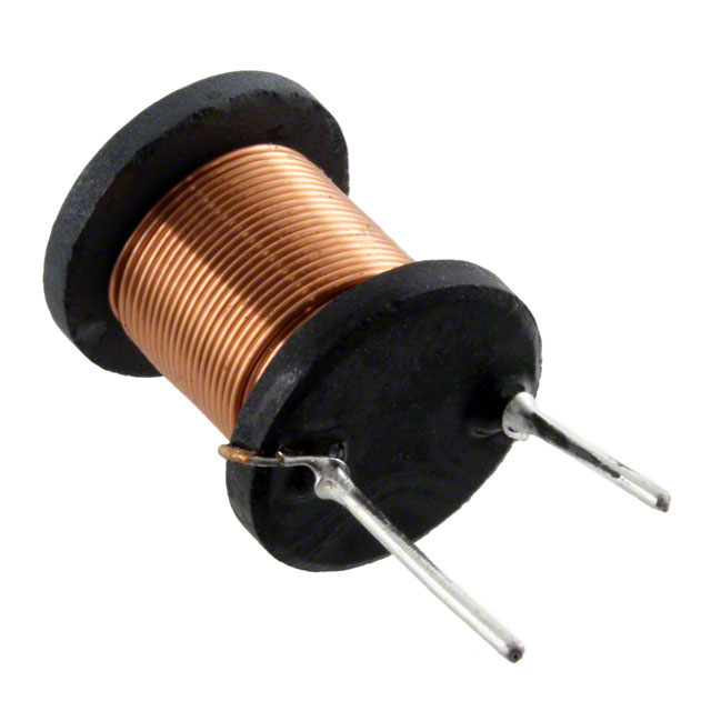
The ELC-18E151L is a 150 µH shielded drum core wirewound inductor manufactured by Panasonic Electronic Components, rated for 2.6 A with 61mOhm DC resistance. This component is classified as obsolete, making identification of functionally equivalent alternatives essential for ongoing design support and procurement continuity. The shielded construction and specific electrical characteristics define the baseline for substitute evaluation.
Substiute Parts
Key Parameters
| Parameter | Value |
|---|---|
| Inductance | 150 µH |
| Inductance Tolerance | ±10% |
| Current Rating | 2.6 A |
| DC Resistance (DCR) | 61mOhm |
| Core Type | Ferrite Drum Core |
| Shielding | Shielded |
| Mounting Type | Through Hole |
| Package | Radial, Vertical Cylinder |
| Inductance Test Frequency | 10 kHz |
| RoHS Status | ROHS3 Compliant |
Substitute Part Grouping Explanation
Substitute identification for the ELC-18E151L is based on the following critical parameters:
- Inductance Value: 150 µH (exact match required)
- Inductance Tolerance: ±10% (matching tolerance band)
- Current Rating: Minimum 2.6 A (equal or higher acceptable)
- Core Material: Ferrite (maintains electromagnetic performance)
- Mounting Type: Through Hole (physical compatibility)
- Package Configuration: Radial, Vertical Cylinder (footprint compatibility)
- RoHS Compliance: ROHS3 Compliant (regulatory requirement)
The AIUR-15-151K from Abracon LLC meets these core substitution criteria. While the substitute exhibits higher DC resistance (110mOhm vs. 61mOhm) and is unshielded versus shielded, these represent functional trade-offs within acceptable engineering parameters for applications where the primary inductance value and current handling capability are the controlling specifications.
Parameter Comparison
| Parameter | ELC-18E151L (Panasonic) | AIUR-15-151K (Abracon) |
|---|---|---|
| Inductance | 150 µH | 150 µH |
| Inductance Tolerance | ±10% | ±10% |
| Current Rating (Amps) | 2.6 A | 2.7 A |
| DC Resistance (DCR) | 61mOhm | 110mOhm Max |
| Core Material | Ferrite | Ferrite |
| Shielding | Shielded | Unshielded |
| Mounting Type | Through Hole | Through Hole |
| Package / Case | Radial, Vertical Cylinder | Radial, Vertical Cylinder (Open) |
| Size / Dimension | 0.748" Dia (19.00mm) | 0.709" Dia (18.00mm) |
| Height - Seated (Max) | 0.988" (25.10mm) | 0.787" (20.00mm) |
| Operating Temperature | Not specified | -25°C ~ 85°C |
| RoHS Status | ROHS3 Compliant | ROHS3 Compliant |
| Inductance Test Frequency | 10 kHz | 1 kHz |
Engineering Selection Recommendations
Primary Substitute: AIUR-15-151K
The AIUR-15-151K qualifies as a functional substitute based on matching inductance value, tolerance, and exceeding the current rating requirement. The component is active in production status, ensuring long-term availability and supply chain stability compared to the obsolete ELC-18E151L.
Selection of the AIUR-15-151K requires evaluation of the following design considerations:
- DC Resistance Increase: The substitute exhibits 110mOhm maximum DCR versus 61mOhm for the original. Applications sensitive to resistive losses or thermal dissipation must account for this 80% increase in series resistance.
- Shielding Difference: The substitute is unshielded. Applications requiring electromagnetic shielding for noise immunity or EMI suppression must assess whether unshielded operation is acceptable.
- Physical Dimensions: The substitute is smaller (18.00mm diameter, 20.00mm height vs. 19.00mm diameter, 25.10mm height), allowing potential PCB layout optimization.
- Regulatory Compliance: Both components meet ROHS3 requirements, supporting equivalent regulatory qualification.
Frequently Asked Questions (FAQ)
Q: Can the AIUR-15-151K directly replace the ELC-18E151L in all applications?
A: Direct replacement is possible for applications where inductance value and current rating are the primary design constraints. However, applications sensitive to DC resistance, thermal performance, or electromagnetic shielding require circuit-level evaluation before substitution.
Q: What is the impact of the higher DC resistance in the AIUR-15-151K?
A: The 110mOhm maximum DCR of the substitute versus 61mOhm of the original results in increased resistive losses. In a 2.6 A circuit, this represents approximately 0.416 W additional power dissipation in the substitute versus 0.410 W in the original. Applications with tight thermal budgets or efficiency requirements must account for this difference.
Q: Does the unshielded design of the AIUR-15-151K affect EMI performance?
A: Unshielded inductors exhibit higher radiated and susceptible EMI characteristics compared to shielded designs. Applications operating in electromagnetically noisy environments or requiring low EMI emissions must evaluate whether unshielded operation meets system-level requirements.
Q: Are the physical dimensions compatible with the original PCB layout?
A: The AIUR-15-151K is smaller than the ELC-18E151L. While the smaller footprint may allow layout optimization, PCB hole spacing and component clearance must be verified against the original design to ensure mechanical compatibility.
Q: What is the difference in inductance test frequency between the two parts?
A: The ELC-18E151L is tested at 10 kHz while the AIUR-15-151K is tested at 1 kHz. Inductance values may vary slightly across frequency ranges due to core material characteristics. For applications operating at specific frequencies, frequency-dependent inductance curves should be consulted.
Q: Are both components RoHS compliant?
A: Yes, both the ELC-18E151L and AIUR-15-151K are ROHS3 compliant, supporting equivalent regulatory qualification for applications subject to RoHS requirements.
Alternative Parts

SJ6012L2TP
Littelfuse Inc.
6 Alternative Parts

JMK107BBJ476MA-RE
Taiyo Yuden
10 Alternative Parts

GMK107BBJ475MA-T
Taiyo Yuden
5 Alternative Parts
SJ6020N2ARP
Littelfuse Inc.
3 Alternative Parts
SJ6025R2ATP
Littelfuse Inc.
4 Alternative Parts

2474-05L
API Delevan Inc.
1 Alternative Parts

4590R-684K
API Delevan Inc.
1 Alternative Parts

CM6560R-334
API Delevan Inc.
1 Alternative Parts

CM6460-104
API Delevan Inc.
1 Alternative Parts

5526-12
API Delevan Inc.
1 Alternative Parts