


Request Quote
(Ships tomorrow)
DMTH43M7LFG-13 Equivalent & Substitute Parts
Part Overview
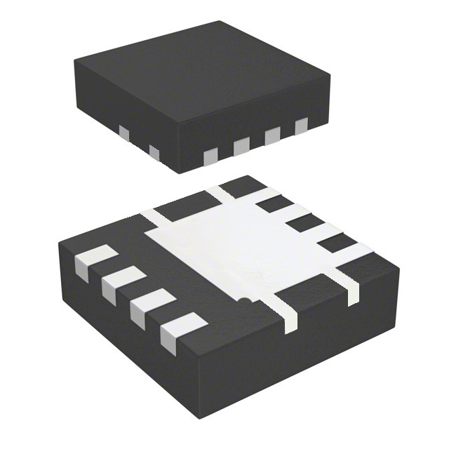
The DMTH43M7LFG-13 is an N-Channel MOSFET manufactured by Diodes Incorporated, rated for 40V drain-to-source voltage with 100A continuous drain current capability. This device is housed in a 8-PowerVDFN surface mount package and is designed for high-current switching applications requiring low on-resistance performance. The part is currently in active production status with 1085 units available in inventory. Substitute parts are identified when equivalent electrical and mechanical parameters are required due to component availability, supply chain constraints, or design flexibility within the same performance envelope.
Substiute Parts
Key Parameters
| Parameter | Value | Unit |
|---|---|---|
| Drain-to-Source Voltage (Vdss) | 40 | V |
| Continuous Drain Current (Id) @ 25°C | 100 | A (Tc) |
| On-Resistance (Rds On Max) @ 20A, 10V | 3 | mOhm |
| Gate Threshold Voltage (Vgs(th) Max) @ 250µA | 2.5 | V |
| Gate Charge (Qg Max) @ 10V | 30 | nC |
| Input Capacitance (Ciss Max) @ 20V | 2182 | pF |
| Power Dissipation (Max) | 3.5 (Ta), 65.2 (Tc) | W |
| Operating Temperature Range | -55 to 175 | °C (TJ) |
| Package Type | 8-PowerVDFN | Surface Mount |
| RoHS Status | ROHS3 Compliant | — |
Substitute Part Grouping Explanation
Substitute parts for the DMTH43M7LFG-13 are identified based on strict electrical and mechanical parameter equivalence. The substitution criteria are limited to the following parameters:
- Drain-to-Source Voltage (Vdss): 40V
- Continuous Drain Current (Id) @ 25°C: 100A (Tc)
- On-Resistance (Rds On Max) @ 20A, 10V: 3mOhm
- Gate Threshold Voltage (Vgs(th) Max) @ 250µA: 2.5V
- Gate Charge (Qg Max) @ 10V: 30nC
- Input Capacitance (Ciss Max) @ 20V: 2182pF
- Power Dissipation (Max): 3.5W (Ta), 65.2W (Tc)
- Operating Temperature Range: -55°C to 175°C (TJ)
- Package Type: 8-PowerVDFN Surface Mount
- RoHS Compliance: ROHS3 Compliant
Parts meeting all these criteria are classified as parametric equivalents and direct substitutes within the same functional category.
Parameter Comparison
| Parameter | DMTH43M7LFG-13 | DMTH43M7LFGQ-7 | Unit |
|---|---|---|---|
| Manufacturer | Diodes Incorporated | Diodes Incorporated | — |
| FET Type | N-Channel | N-Channel | — |
| Technology | MOSFET (Metal Oxide) | MOSFET (Metal Oxide) | — |
| Drain-to-Source Voltage (Vdss) | 40 | 40 | V |
| Continuous Drain Current (Id) @ 25°C | 100 | 100 | A (Tc) |
| On-Resistance (Rds On Max) @ 20A, 10V | 3 | 3 | mOhm |
| Gate Threshold Voltage (Vgs(th) Max) @ 250µA | 2.5 | 2.5 | V |
| Gate Charge (Qg Max) @ 10V | 30 | 30 | nC |
| Input Capacitance (Ciss Max) @ 20V | 2182 | 2182 | pF |
| Power Dissipation (Max) | 3.5 (Ta), 65.2 (Tc) | 3.5 (Ta), 65.2 (Tc) | W |
| Operating Temperature Range | -55 to 175 | -55 to 175 | °C (TJ) |
| Package Type | 8-PowerVDFN | 8-PowerVDFN | Surface Mount |
| Packaging Format | Tape & Reel (TR) | Tape & Reel (TR) | — |
| RoHS Status | ROHS3 Compliant | ROHS3 Compliant | — |
| REACH Status | REACH Unaffected | REACH Unaffected | — |
| Product Status | Active | Active | — |
| Inventory Available | 1085 | 1071 | Pcs |
Engineering Selection Recommendations
Both the DMTH43M7LFG-13 and DMTH43M7LFGQ-7 are active production parts from Diodes Incorporated with identical electrical and mechanical specifications. Selection between these parts is based on the following factors:
Product Status and Compliance: Both parts maintain active production status and are fully compliant with ROHS3 and REACH regulations, ensuring long-term availability and regulatory alignment.
Automotive Qualification: The DMTH43M7LFGQ-7 carries AEC-Q101 automotive qualification, making it suitable for automotive applications requiring formal qualification documentation. The DMTH43M7LFG-13 does not carry this designation and is appropriate for industrial and consumer applications.
Inventory Availability: The DMTH43M7LFG-13 has 1085 units in stock, while the DMTH43M7LFGQ-7 has 1071 units available. Both maintain adequate inventory levels for production requirements.
Package and Thermal Performance: Both parts utilize the 8-PowerVDFN surface mount package with identical thermal and electrical performance characteristics, ensuring direct pin-for-pin compatibility and equivalent thermal management in PCB layouts.
Selection should prioritize the DMTH43M7LFGQ-7 for automotive applications requiring AEC-Q101 compliance. For non-automotive applications, either part is suitable based on availability and supply chain requirements.
Frequently Asked Questions (FAQ)
Q: Can the DMTH43M7LFGQ-7 be used as a direct replacement for the DMTH43M7LFG-13?
A: Yes. Both parts are parametric equivalents with identical electrical specifications, on-resistance, gate charge, and thermal performance. They share the same 8-PowerVDFN package and are pin-for-pin compatible. No circuit modifications are required for substitution.
Q: What is the primary difference between these two part numbers?
A: The DMTH43M7LFGQ-7 carries AEC-Q101 automotive qualification, while the DMTH43M7LFG-13 does not. All other electrical and mechanical parameters are identical. The qualification designation determines suitability for automotive versus industrial/consumer applications.
Q: Are both parts suitable for high-current switching applications?
A: Yes. Both parts are rated for 100A continuous drain current with 3mOhm on-resistance at 20A and 10V gate-source voltage. They are designed for high-current switching applications requiring low conduction losses.
Q: What is the operating temperature range for these MOSFETs?
A: Both parts operate across a junction temperature range of -55°C to 175°C (TJ), providing performance across industrial and extended temperature applications.
Q: Are these parts available in different packaging formats?
A: Both parts are supplied in Tape & Reel (TR) format for automated assembly. The 8-PowerVDFN package is the only available configuration for these part numbers.
Q: Do these parts meet environmental compliance standards?
A: Yes. Both the DMTH43M7LFG-13 and DMTH43M7LFGQ-7 are ROHS3 compliant and REACH unaffected, meeting current environmental and regulatory requirements for electronic components.
Q: What is the gate charge specification, and why is it important?
A: The gate charge (Qg) is specified as 30nC maximum at 10V. This parameter determines the switching speed and gate drive requirements. Lower gate charge enables faster switching transitions and reduces gate driver power consumption.
Q: Can these parts be used in parallel for higher current applications?
A: Parallel operation is not addressed in the provided specifications. Circuit design considerations for parallel FET configurations require additional analysis beyond the scope of this parametric equivalence document.
Alternative Parts

SJ6012L2TP
Littelfuse Inc.
6 Alternative Parts

JMK107BBJ476MA-RE
Taiyo Yuden
10 Alternative Parts

GMK107BBJ475MA-T
Taiyo Yuden
5 Alternative Parts
SJ6020N2ARP
Littelfuse Inc.
3 Alternative Parts
SJ6025R2ATP
Littelfuse Inc.
4 Alternative Parts

2474-05L
API Delevan Inc.
1 Alternative Parts

4590R-684K
API Delevan Inc.
1 Alternative Parts

CM6560R-334
API Delevan Inc.
1 Alternative Parts

CM6460-104
API Delevan Inc.
1 Alternative Parts

5526-12
API Delevan Inc.
1 Alternative Parts