


Request Quote
(Ships tomorrow)
DMT31M7LPS-13 Equivalent & Substitute Parts
Part Overview
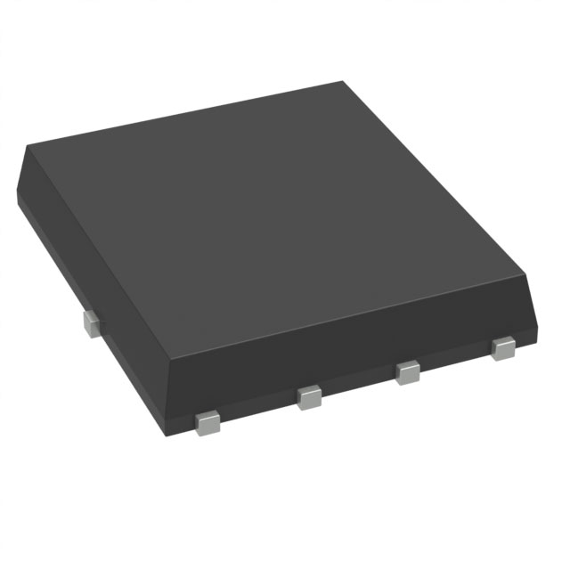
The DMT31M7LPS-13 is an N-Channel MOSFET manufactured by Diodes Incorporated, rated for 30V drain-to-source voltage with 30A continuous drain current at 25°C (Ta) and 100A at case temperature (Tc). This device is housed in a Surface Mount PowerDI5060-8 package and is classified as Active product status. The part is ROHS3 compliant with MSL 1 (Unlimited) moisture sensitivity rating.
Equivalent and substitute parts are identified when alternative MOSFETs meet or exceed the electrical specifications and mechanical compatibility requirements of the original part, enabling design flexibility, inventory optimization, and supply chain continuity.
Substiute Parts
Key Parameters
| Parameter | Value | Unit |
|---|---|---|
| Drain-to-Source Voltage (Vdss) | 30 | V |
| Continuous Drain Current @ 25°C (Ta) | 30 | A |
| Continuous Drain Current @ Case Temp (Tc) | 100 | A |
| On-Resistance (Rds On Max) @ 20A, 10V | 1.7 | mOhm |
| Gate Threshold Voltage (Vgs(th) Max) @ 250µA | 3 | V |
| Gate Charge (Qg Max) @ 10V | 90 | nC |
| Input Capacitance (Ciss Max) @ 15V | 5741 | pF |
| Power Dissipation (Ta) | 1.3 | W |
| Power Dissipation (Tc) | 113 | W |
| Operating Temperature Range | -55 to 150 | °C (TJ) |
| Mounting Type | Surface Mount | — |
| Package | 8-PowerTDFN | — |
| RoHS Status | ROHS3 Compliant | — |
| MSL Rating | 1 (Unlimited) | — |
Substitute Part Grouping Explanation
Substitute parts for the DMT31M7LPS-13 are identified based on the following electrical and mechanical criteria:
Electrical Compatibility Requirements:
- Drain-to-Source Voltage (Vdss) equal to or greater than 30V
- Continuous Drain Current (Id @ 25°C) equal to or greater than 30A
- Gate Threshold Voltage (Vgs(th)) within compatible operating range
- On-Resistance (Rds On) performance suitable for the application thermal environment
- Operating temperature range encompassing -55°C to 150°C
Mechanical Compatibility Requirements:
- Surface Mount technology
- Pin configuration compatible with PowerDI5060-8 or equivalent footprint
- Package classification as 8-PowerTDFN or functionally equivalent
Compliance Requirements:
- ROHS3 compliance
- MSL rating of 1 (Unlimited) or equivalent
- Active product status
The FDMS8018 from onsemi meets these criteria and is classified as a manufacturer-recommended substitute.
Parameter Comparison
| Parameter | DMT31M7LPS-13 (Diodes Inc.) | FDMS8018 (onsemi) | Unit |
|---|---|---|---|
| Manufacturer | Diodes Incorporated | onsemi | — |
| FET Type | N-Channel | N-Channel | — |
| Technology | MOSFET (Metal Oxide) | MOSFET (Metal Oxide) | — |
| Drain-to-Source Voltage (Vdss) | 30 | 30 | V |
| Continuous Drain Current @ 25°C (Ta) | 30 | 30 | A |
| Continuous Drain Current @ Case Temp (Tc) | 100 | 120 | A |
| On-Resistance (Rds On Max) | 1.7 @ 20A, 10V | 1.8 @ 30A, 10V | mOhm |
| Gate Threshold Voltage (Vgs(th) Max) @ 250µA | 3 | 3 | V |
| Gate Charge (Qg Max) @ 10V | 90 | 61 | nC |
| Input Capacitance (Ciss Max) @ 15V | 5741 | 5235 | pF |
| Power Dissipation (Ta) | 1.3 | 2.5 | W |
| Power Dissipation (Tc) | 113 | 83 | W |
| Operating Temperature Range | -55 to 150 | -55 to 150 | °C (TJ) |
| Mounting Type | Surface Mount | Surface Mount | — |
| Package / Case | 8-PowerTDFN | 8-PowerTDFN | — |
| RoHS Status | ROHS3 Compliant | ROHS3 Compliant | — |
| MSL Rating | 1 (Unlimited) | 1 (Unlimited) | — |
| Product Status | Active | Active | — |
Engineering Selection Recommendations
DMT31M7LPS-13 (Primary Part): The DMT31M7LPS-13 remains the primary selection when Diodes Incorporated supply chain and part traceability are required. This part is Active status with full ROHS3 compliance and MSL 1 rating. Current inventory of 684 pieces supports immediate availability.
FDMS8018 (Substitute Part): The FDMS8018 from onsemi is a qualified substitute meeting all electrical and mechanical requirements. Key advantages include higher continuous drain current at case temperature (120A vs. 100A), lower gate charge (61 nC vs. 90 nC), and reduced input capacitance (5235 pF vs. 5741 pF). The FDMS8018 is Active status with ROHS3 compliance and MSL 1 rating. Inventory availability is 45,200 pieces, providing extended supply security.
Both parts are suitable for applications requiring 30V N-Channel MOSFETs in Surface Mount PowerDI5060-8 packages with operating temperatures from -55°C to 150°C. Selection between the two parts is determined by supply chain requirements, inventory availability, and design-specific performance priorities.
Frequently Asked Questions (FAQ)
Q: Can the FDMS8018 directly replace the DMT31M7LPS-13 in existing designs?
A: Yes. Both parts share identical Vdss (30V), Ta continuous drain current (30A), gate threshold voltage (3V @ 250µA), operating temperature range (-55°C to 150°C), and package classification (8-PowerTDFN Surface Mount). The FDMS8018 meets or exceeds all critical electrical parameters of the DMT31M7LPS-13.
Q: What are the key differences between these two parts?
A: The FDMS8018 provides higher Tc continuous drain current (120A vs. 100A), lower gate charge (61 nC vs. 90 nC), and reduced input capacitance (5235 pF vs. 5741 pF). On-resistance is comparable (1.8 mOhm vs. 1.7 mOhm). These differences result in improved switching performance and reduced gate drive requirements for the FDMS8018.
Q: Are both parts RoHS compliant?
A: Yes. Both the DMT31M7LPS-13 and FDMS8018 are ROHS3 compliant with MSL 1 (Unlimited) moisture sensitivity ratings.
Q: What is the package compatibility between these parts?
A: Both parts use 8-PowerTDFN Surface Mount packages. The DMT31M7LPS-13 is supplied in Tape & Reel (TR) packaging, while the FDMS8018 is available in Cut Tape (CT) and Digi-Reel® formats. PCB footprints are compatible.
Q: Which part should be selected for new designs?
A: Selection is based on supply chain strategy and performance requirements. The FDMS8018 offers superior gate charge and capacitance characteristics, making it advantageous for high-frequency switching applications. The DMT31M7LPS-13 is appropriate when Diodes Incorporated sourcing is mandated or preferred.
Q: Are there any thermal considerations when substituting these parts?
A: Both parts operate across -55°C to 150°C junction temperature range. The FDMS8018 exhibits lower power dissipation at case temperature (83W vs. 113W), providing thermal advantages in high-current applications. Thermal design should account for the specific application environment and heat dissipation requirements.
Q: What is the gate drive voltage requirement for both parts?
A: Both parts specify maximum gate-source voltage (Vgs) of ±20V with drive voltage options at 4.5V and 10V for maximum on-resistance specification. Gate drive circuits must be compatible with these voltage levels.
Alternative Parts

SJ6012L2TP
Littelfuse Inc.
6 Alternative Parts

JMK107BBJ476MA-RE
Taiyo Yuden
10 Alternative Parts

GMK107BBJ475MA-T
Taiyo Yuden
5 Alternative Parts
SJ6020N2ARP
Littelfuse Inc.
3 Alternative Parts
SJ6025R2ATP
Littelfuse Inc.
4 Alternative Parts

2474-05L
API Delevan Inc.
1 Alternative Parts

4590R-684K
API Delevan Inc.
1 Alternative Parts

CM6560R-334
API Delevan Inc.
1 Alternative Parts

CM6460-104
API Delevan Inc.
1 Alternative Parts

5526-12
API Delevan Inc.
1 Alternative Parts