


Request Quote
(Ships tomorrow)
DMS3014SFG-13 Equivalent & Substitute Parts
Part Overview
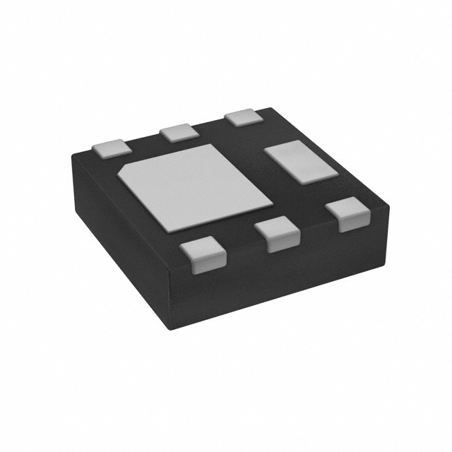
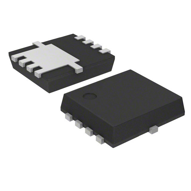
The DMS3014SFG-13 is an N-Channel MOSFET manufactured by Diodes Incorporated, rated for 30 V drain-to-source voltage with 9.5 A continuous drain current at 25°C. This device is housed in a PowerDI3333-8 surface mount package and features a built-in Schottky diode. The part is classified as Active and carries AEC-Q101 automotive qualification.
Substitute parts are identified when equivalent electrical performance and mechanical compatibility can be maintained within the specified parameter ranges. Alternative models may be required due to inventory constraints, packaging preferences, or design optimization for improved thermal performance or gate charge characteristics.
Substiute Parts
Key Parameters
| Parameter | Value | Unit |
|---|---|---|
| Drain-to-Source Voltage (Vdss) | 30 | V |
| Continuous Drain Current (Id) @ 25°C | 9.5 | A (Ta) |
| On-Resistance (Rds On Max) @ 10V | 13 | mOhm |
| Gate Threshold Voltage (Vgs(th) Max) | 2.2 | V @ 250µA |
| Gate Charge (Qg Max) @ 10V | 45.7 | nC |
| Power Dissipation (Max) | 1 | W (Ta) |
| Operating Temperature Range | -55 to 150 | °C (TJ) |
| Package Type | 8-PowerVDFN | PowerDI3333-8 |
| Qualification | AEC-Q101 | Automotive |
Substitute Part Grouping Explanation
Substitution eligibility for the DMS3014SFG-13 is determined by the following critical parameters:
Electrical Compatibility Criteria:
- Drain-to-Source Voltage (Vdss) must equal or exceed 30 V
- Continuous Drain Current (Id) must meet or exceed 9.5 A at 25°C
- Gate Threshold Voltage (Vgs(th)) must be compatible with 2.2 V maximum specification
- Maximum Gate Supply Voltage (Vgs Max) must accommodate ±12 V operation
- Operating temperature range must span -55°C to 150°C (TJ)
Mechanical Compatibility Criteria:
- Surface mount mounting type required
- Package footprint compatibility with 8-pin configurations
- RoHS3 compliance and MSL 1 (Unlimited) moisture sensitivity level
Compliance Requirements:
- RoHS3 Compliant status
- REACH Unaffected classification
- Automotive-grade qualification preferred but not mandatory for all substitutes
The identified substitute parts maintain these core electrical and mechanical parameters while offering variations in gate charge, input capacitance, and power dissipation characteristics that may provide design optimization benefits.
Parameter Comparison
| Parameter | DMS3014SFG-13 | DMN3021LFDF-7 | RQ3E100GNTB | RQ3E100MNTB1 | Unit |
|---|---|---|---|---|---|
| Manufacturer | Diodes Inc. | Diodes Inc. | Rohm Semi. | Rohm Semi. | — |
| Vdss | 30 | 30 | 30 | 30 | V |
| Id @ 25°C | 9.5 | 11.8 | 10 | 10 | A (Ta) |
| Rds On (Max) @ 10V | 13 | 15 | 11.7 | 12.3 | mOhm |
| Vgs(th) (Max) | 2.2 | 2.2 | 2.5 | 2.5 | V @ specified Id |
| Qg (Max) @ 10V | 45.7 | 14 | 7.9 | 9.9 | nC |
| Ciss (Max) @ 15V | 4310 | 706 | 420 | 520 | pF |
| Power Dissipation (Max) | 1 (Ta) | 2.03 (Ta) | 2 (Ta) / 15 (Tc) | 2 (Ta) | W |
| Vgs (Max) | ±12 | ±20 | ±20 | ±20 | V |
| Operating Temp Range | -55 to 150 | -55 to 150 | to 150 | to 150 | °C (TJ) |
| Package | 8-PowerVDFN | 6-UDFN Exposed Pad | 8-PowerVDFN | 8-PowerVDFN | — |
| Product Status | Active | Active | Active | Not For New Designs | — |
| RoHS3 Compliant | Yes | Yes | Yes | Yes | — |
Engineering Selection Recommendations
DMN3021LFDF-7 (Diodes Incorporated)
This substitute provides higher continuous drain current (11.8 A versus 9.5 A) and improved power dissipation capability (2.03 W versus 1 W). The device maintains identical Vdss and Vgs(th) specifications. Significantly reduced gate charge (14 nC versus 45.7 nC) and input capacitance (706 pF versus 4310 pF) enable faster switching performance. The 6-UDFN package differs from the original 8-PowerVDFN footprint and requires PCB layout modification. Product status is Active. This substitute is suitable for designs requiring enhanced thermal performance or reduced switching losses.
RQ3E100GNTB (Rohm Semiconductor)
This substitute maintains 30 V Vdss and 10 A continuous drain current with superior on-resistance (11.7 mOhm versus 13 mOhm). Gate charge is substantially lower (7.9 nC versus 45.7 nC), and input capacitance is reduced to 420 pF. The device supports higher gate supply voltage (±20 V versus ±12 V). Power dissipation reaches 2 W at Ta and 15 W at Tc, providing thermal margin. The 8-PowerVDFN package maintains mechanical compatibility with the original part. Product status is Active. This substitute offers improved switching efficiency and is recommended for new designs.
RQ3E100MNTB1 (Rohm Semiconductor)
This substitute provides equivalent electrical performance to RQ3E100GNTB with 10 A continuous drain current and 12.3 mOhm on-resistance. Gate charge (9.9 nC) and input capacitance (520 pF) remain significantly lower than the original part. The 8-PowerVDFN package maintains mechanical compatibility. However, product status is designated as "Not For New Designs," indicating this part is in mature or end-of-life phase. This substitute is suitable only for replacement or legacy system applications where design continuity is required.
Frequently Asked Questions (FAQ)
Q: Can DMN3021LFDF-7 be used as a direct replacement for DMS3014SFG-13?
A: DMN3021LFDF-7 provides superior electrical performance but uses a different package (6-UDFN versus 8-PowerVDFN). PCB layout modification is required. Electrical parameters are compatible within the specified ranges.
Q: What is the primary advantage of RQ3E100GNTB over the original DMS3014SFG-13?
A: RQ3E100GNTB offers significantly lower gate charge (7.9 nC versus 45.7 nC) and reduced input capacitance (420 pF versus 4310 pF), resulting in faster switching transitions and lower gate drive power requirements. On-resistance is also improved (11.7 mOhm versus 13 mOhm).
Q: Why is RQ3E100MNTB1 marked "Not For New Designs"?
A: This designation indicates the part is in mature production phase with limited future availability. While electrically equivalent to RQ3E100GNTB, it should be used only for replacement applications or legacy system support. New designs should utilize RQ3E100GNTB or DMN3021LFDF-7.
Q: Are all substitute parts AEC-Q101 qualified?
A: The original DMS3014SFG-13 carries AEC-Q101 automotive qualification. Substitute parts DMN3021LFDF-7 and RQ3E100GNTB are Active products with RoHS3 compliance and REACH Unaffected status. Specific automotive qualification details for substitutes should be verified against application requirements.
Q: What is the impact of different gate charge values on circuit design?
A: Gate charge directly affects gate drive circuit requirements and switching speed. Lower gate charge (7.9 nC in RQ3E100GNTB versus 45.7 nC in DMS3014SFG-13) reduces gate drive power dissipation and enables faster switching transitions. This may require gate driver circuit optimization.
Q: Can the 6-UDFN package of DMN3021LFDF-7 be accommodated in existing PCB layouts designed for 8-PowerVDFN?
A: No. The 6-UDFN Exposed Pad package has different pin count and footprint dimensions. PCB redesign is required, including trace routing and thermal via placement modifications.
Q: What are the moisture sensitivity implications for these parts?
A: All listed parts carry MSL 1 (Unlimited) classification, indicating unlimited shelf life without moisture control requirements. Standard handling procedures apply without special desiccant packaging or baking requirements.
Q: How do the power dissipation ratings compare across substitute options?
A: DMS3014SFG-13 is rated 1 W (Ta). DMN3021LFDF-7 provides 2.03 W (Ta), RQ3E100GNTB provides 2 W (Ta) and 15 W (Tc), and RQ3E100MNTB1 provides 2 W (Ta). Higher power dissipation ratings indicate improved thermal capability for high-current applications.
Alternative Parts

SJ6012L2TP
Littelfuse Inc.
6 Alternative Parts

JMK107BBJ476MA-RE
Taiyo Yuden
10 Alternative Parts

GMK107BBJ475MA-T
Taiyo Yuden
5 Alternative Parts
SJ6020N2ARP
Littelfuse Inc.
3 Alternative Parts
SJ6025R2ATP
Littelfuse Inc.
4 Alternative Parts

2474-05L
API Delevan Inc.
1 Alternative Parts

4590R-684K
API Delevan Inc.
1 Alternative Parts

CM6560R-334
API Delevan Inc.
1 Alternative Parts

CM6460-104
API Delevan Inc.
1 Alternative Parts

5526-12
API Delevan Inc.
1 Alternative Parts