


Request Quote
(Ships tomorrow)
DKI06261 Equivalent & Substitute Parts Reference
Part Overview
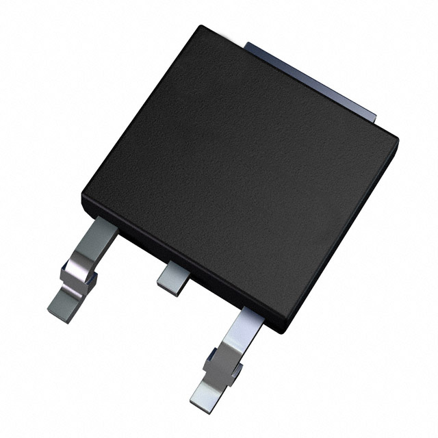
The DKI06261 is an N-Channel MOSFET with a drain-to-source voltage of 60 V and a continuous drain current of 25 A (Tc), provided in a TO-252 surface-mount package. With a maximum on-state resistance (Rds On) of 21.2 mOhm at 12.5A, 10V, it features a gate threshold voltage of 2.5V and a maximum gate charge of 16 nC. The product is RoHS compliant and has an MSL of 1. This MOSFET is classified as obsolete, which necessitates the identification of replacement models that match the electrical, thermal, and mechanical criteria for direct substitution in existing designs.
Substiute Parts
Key Parameters
| Parameter | Value |
|---|---|
| FET Type | N-Channel |
| Technology | MOSFET (Metal Oxide) |
| Drain to Source Voltage (Vdss) | 60 V |
| Current - Continuous Drain (Id) @ 25°C | 25A (Tc) |
| Drive Voltage (Max Rds On, Min Rds On) | 4.5V, 10V |
| Rds On (Max) @ Id, Vgs | 21.2mOhm @ 12.5A, 10V |
| Vgs(th) (Max) @ Id | 2.5V @ 250µA |
| Gate Charge (Qg) (Max) @ Vgs | 16 nC @ 10V |
| Vgs (Max) | ±20V |
| Input Capacitance (Ciss) (Max) @ Vds | 1050 pF @ 25 V |
| Power Dissipation (Max) | 32W (Tc) |
| Operating Temperature | 150°C (TJ) |
| Mounting Type | Surface Mount |
| Supplier Device Package | TO-252 |
| Package / Case | TO-252-3, DPAK (2 Leads + Tab), SC-63 |
| RoHS Status | RoHS Compliant |
| MSL | 1 (Unlimited) |
| Product Status | Obsolete |
Substitute Part Grouping Explanation
Substitute MOSFETs are selected according to electrical and mechanical parameters that directly impact compatibility:
- FET Type and Technology (N-Channel MOSFET)
- Drain to Source Voltage (Vdss)
- Continuous Drain Current (Id)
- Drive Voltage for Rds On
- Rds On (Max)
- Gate threshold voltage (Vgs(th))
- Maximum Gate Charge (Qg)
- Vgs (Max)
- Input Capacitance (Ciss)
- Power Dissipation (Max)
- Operating Temperature Range
- Mounting Type and Package
- Compliance (RoHS, MSL)
- Product Status
These key electrical and mechanical attributes must be matched or exceeded to qualify as a functional substitute in this product category.
Parameter Comparison
| Parameter | DKI06261 (Sanken) |
IPD30N06S2L23ATMA3 (Infineon) |
IPD30N08S2L21ATMA1 (Infineon) |
RD3L220SNTL1 (Rohm) |
STD35NF06LT4 (STMicro) |
TK25S06N1L,LXHQ (Toshiba) |
|---|---|---|---|---|---|---|
| FET Type | N-Channel | N-Channel | N-Channel | N-Channel | N-Channel | N-Channel |
| Technology | MOSFET (Metal Oxide) | MOSFET (Metal Oxide) | MOSFET (Metal Oxide) | MOSFET (Metal Oxide) | MOSFET (Metal Oxide) | MOSFET (Metal Oxide) |
| Drain to Source Voltage (Vdss) | 60 V | 55 V | 75 V | 60 V | 60 V | 60 V |
| Current - Continuous Drain (Id) @ 25°C | 25A (Tc) | 30A (Tc) | 30A (Tc) | 22A (Ta) | 35A (Tc) | 25A (Ta) |
| Drive Voltage (Max Rds On, Min Rds On) | 4.5V, 10V | 4.5V, 10V | 4.5V, 10V | 4V, 10V | 4.5V, 10V | 4.5V, 10V |
| Rds On (Max) @ Id, Vgs | 21.2mOhm @ 12.5A, 10V | 23mOhm @ 22A, 10V | 20.5mOhm @ 25A, 10V | 26mOhm @ 22A, 10V | 17mOhm @ 17.5A, 10V | 36.8mOhm @ 12.5A, 4.5V |
| Vgs(th) (Max) @ Id | 2.5V @ 250µA | 2V @ 50µA | 2V @ 80µA | 3V @ 1mA | 2.5V @ 250µA | 2.5V @ 100µA |
| Gate Charge (Qg) (Max) @ Vgs | 16 nC @ 10 V | 42 nC @ 10 V | 72 nC @ 10 V | 30 nC @ 10 V | 33 nC @ 4.5 V | 15 nC @ 10 V |
| Vgs (Max) | ±20V | ±20V | ±20V | ±20V | ±16V | ±20V |
| Input Capacitance (Ciss) (Max) | 1050 pF @ 25 V | 1091 pF @ 25 V | 1650 pF @ 25 V | 1500 pF @ 10 V | 1700 pF @ 25 V | 855 pF @ 10 V |
| Power Dissipation (Max) | 32W (Tc) | 100W (Tc) | 136W (Tc) | 20W (Tc) | 80W (Tc) | 57W (Tc) |
| Operating Temperature | 150°C (TJ) | -55°C ~ 175°C (TJ) | -55°C ~ 175°C (TJ) | 150°C (TJ) | -55°C ~ 175°C (TJ) | 175°C |
| Mounting Type | Surface Mount | Surface Mount | Surface Mount | Surface Mount | Surface Mount | Surface Mount |
| Supplier Device Package | TO-252 | PG-TO252-3-11 | PG-TO252-3-11 | TO-252 | DPAK | DPAK+ |
| Package / Case | TO-252-3, DPAK (2 Leads + Tab), SC-63 |
TO-252-3, DPAK (2 Leads + Tab), SC-63 |
TO-252-3, DPAK (2 Leads + Tab), SC-63 |
TO-252-3, DPAK (2 Leads + Tab), SC-63 |
TO-252-3, DPAK (2 Leads + Tab), SC-63 |
TO-252-3, DPAK (2 Leads + Tab), SC-63 |
| RoHS Status | RoHS Compliant | ROHS3 Compliant | ROHS3 Compliant | ROHS3 Compliant | ROHS3 Compliant | - |
| MSL | 1 (Unlimited) | 1 (Unlimited) | 1 (Unlimited) | 1 (Unlimited) | 1 (Unlimited) | 1 (Unlimited) |
| Product Status | Obsolete | Active | Active | Active | Active | Active |
Engineering Selection Recommendations
When selecting replacements for the DKI06261, preference should be given to parts with active status, equivalent RoHS compliance, and matching MSL grade. All alternatives provided have the required N-channel MOSFET technology and surface-mount TO-252/DPAK-compatible packages. RoHS compliance and MSL ratings are specified for each substitute, supporting compatibility with standard moisture control and global environmental regulations.
Frequently Asked Questions (FAQ)
Q1: What criteria are used to determine compatible substitute MOSFETs?
A1: Substitutes are selected based on matching key parameters: FET type, technology, drain-to-source voltage (Vdss), continuous drain current (Id), Rds On, gate threshold voltage (Vgs(th)), drive voltage, package compatibility, power dissipation, and compliance certifications.
Q2: Can I use any MOSFET in a TO-252 package as a substitute?
A2: Only MOSFETs that closely match the electrical parameters (Vdss, Id, Rds On, Vgs, etc.) and mechanical packaging (footprint, leads) of the DKI06261 are suitable substitutes.
Q3: Do substitute parts support RoHS compliance and the same moisture sensitivity?
A3: Substitute parts listed have documented RoHS compliance and MSL 1, matching the original DKI06261.
Q4: How important is drive voltage and gate charge (Qg) in substitution?
A4: Drive voltage must align to ensure on-state performance; gate charge affects switching behavior, and both should be within application-compatible ranges.
Q5: What is the effect of substituting a part with different power dissipation or operating temperature?
A5: Substitutes with equal or higher power dissipation and operating temperature range are compatible for thermal management and reliability, provided all other parameters match.
Q6: Are all mechanical and package considerations identical among the substitutes?
A6: All substitutes feature surface-mount TO-252, DPAK, or PG-TO252-3-11 cases, offering mechanical compatibility for PCB layout and assembly.
Alternative Parts

SJ6012L2TP
Littelfuse Inc.
6 Alternative Parts

JMK107BBJ476MA-RE
Taiyo Yuden
10 Alternative Parts

GMK107BBJ475MA-T
Taiyo Yuden
5 Alternative Parts
SJ6020N2ARP
Littelfuse Inc.
3 Alternative Parts
SJ6025R2ATP
Littelfuse Inc.
4 Alternative Parts

2474-05L
API Delevan Inc.
1 Alternative Parts

4590R-684K
API Delevan Inc.
1 Alternative Parts

CM6560R-334
API Delevan Inc.
1 Alternative Parts

CM6460-104
API Delevan Inc.
1 Alternative Parts

5526-12
API Delevan Inc.
1 Alternative Parts