


Request Quote
(Ships tomorrow)
DG201BDJ Equivalent & Substitute Parts Reference
Part Overview
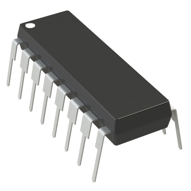
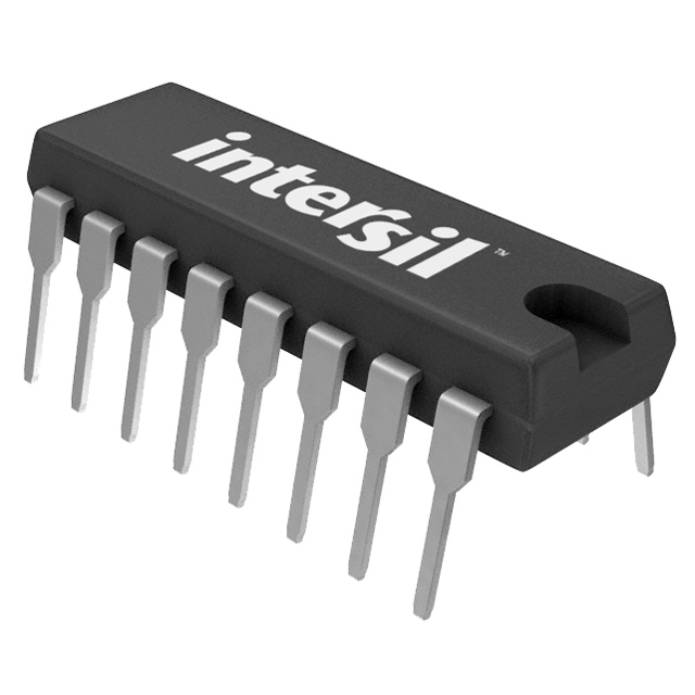
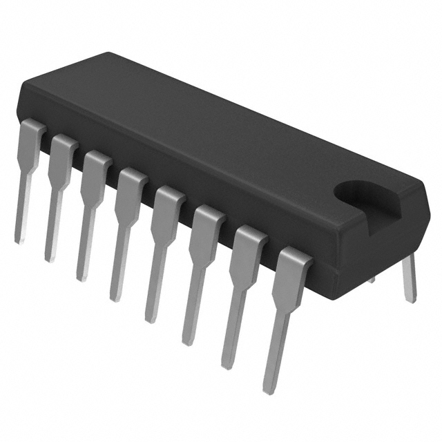
The DG201BDJ is a 4-circuit SPST-NC (Single Pole Single Throw - Normally Closed) analog switch IC manufactured by Vishay Siliconix in a 16-DIP package. This component functions as a precision electronic switch with 85Ohm on-state resistance, designed for signal routing and multiplexing applications across industrial and commercial systems.
The DG201BDJ carries an obsolete product status. Identifying equivalent and substitute parts is necessary to maintain design continuity, ensure supply chain availability, and support long-term product support for legacy systems utilizing this interface component.
Substiute Parts
Key Parameters
| Parameter | Value | Unit | Significance for Substitution |
|---|---|---|---|
| Switch Circuit Type | SPST - NC | — | Defines switch topology; substitutes must match |
| Number of Circuits | 4 | — | Channel count; critical for pin compatibility |
| Multiplexer/Demultiplexer Circuit | 1:1 | — | Switching configuration; must remain consistent |
| On-State Resistance (Max) | 85 | Ohm | Primary electrical parameter; affects signal integrity |
| Channel-to-Channel Matching (ΔRon) | 2 | Ohm | Resistance uniformity across channels |
| Voltage - Supply, Single (V+) | 4.5V ~ 25V | V | Operating voltage range; critical for circuit design |
| Voltage - Supply, Dual (V±) | ±4.5V ~ 22V | V | Dual supply capability; determines power architecture |
| Switch Time (Ton, Toff) (Max) | 300ns, 200ns | ns | Switching speed; affects signal bandwidth |
| Charge Injection | 1 | pC | Signal distortion parameter |
| Channel Capacitance (CS(off), CD(off)) | 5pF, 5pF | pF | Off-state capacitance; affects crosstalk |
| Current - Leakage (IS(off)) (Max) | 500 | pA | Off-state leakage; signal integrity parameter |
| Crosstalk | -95 | dB @ 100kHz | Channel isolation; critical for multi-channel applications |
| Operating Temperature | -40°C ~ 85°C | °C | Thermal operating range |
| Package / Case | 16-DIP (0.300", 7.62mm) | — | Physical form factor; determines PCB compatibility |
| Mounting Type | Through Hole | — | Assembly method; affects board design |
| RoHS Status | RoHS non-compliant | — | Regulatory compliance; affects procurement |
Substitute Part Grouping Explanation
Substitution of the DG201BDJ is determined by strict adherence to the following electrical and mechanical parameters:
Primary Substitution Criteria:
- Switch circuit topology must be SPST - NC
- Number of circuits must equal 4
- Multiplexer configuration must be 1:1
- Package must be 16-DIP (0.300", 7.62mm)
- Mounting type must be Through Hole
Secondary Electrical Parameters (Allowable Variation):
- On-state resistance (Ron): Substitutes may vary from the 85Ohm specification, provided the application circuit tolerates the difference
- Supply voltage ranges: Substitutes may have different voltage specifications; circuit design must accommodate the substitute's voltage requirements
- Switch timing (Ton, Toff): Variations are acceptable if system bandwidth requirements are met
- Charge injection, capacitance, leakage current, and crosstalk: These parameters may differ; system performance must be validated against substitute specifications
Regulatory and Compliance Parameters:
- RoHS compliance status may differ between original and substitute parts
- Operating temperature range must encompass the application's thermal requirements
Substitutes are grouped by on-state resistance value, as this parameter most directly affects signal path characteristics and circuit performance.
Parameter Comparison
| Part Number | Manufacturer | Ron (Max) Ohm | ΔRon Ohm | V+ Range | V± Range | Ton/Toff (Max) ns | Charge Injection pC | Leakage (Max) pA | Crosstalk dB | Status | RoHS |
|---|---|---|---|---|---|---|---|---|---|---|---|
| DG201BDJ | Vishay Siliconix | 85 | 2 | 4.5V ~ 25V | ±4.5V ~ 22V | 300, 200 | 1 | 500 | -95 @ 100kHz | Obsolete | Non-compliant |
| DG201BDJ-E3 | Vishay Siliconix | 85 | 2 | 4.5V ~ 25V | ±4.5V ~ 22V | 300, 200 | 1 | 500 | -95 @ 100kHz | Active | ROHS3 Compliant |
| ADG201AKNZ | Analog Devices Inc. | 90 | 4.5 | 10V ~ 15V | ±10V ~ 15V | 300, 250 | 20 | 2000 | -80 @ 100kHz | Active | ROHS3 Compliant |
| ADG201HSJNZ | Analog Devices Inc. | 50 | 1.5 | 10.8V ~ 16.5V | ±13.5V ~ 16.5V | 75, 75 | 10 | 1000 | -86 @ 100kHz | Active | ROHS3 Compliant |
| ADG201HSKNZ | Analog Devices Inc. | 50 | 1.5 | 10.8V ~ 16.5V | ±13.5V ~ 16.5V | 50, 50 | 10 | 1000 | -86 @ 100kHz | Active | ROHS3 Compliant |
| ALD4211PCL | Advanced Linear Devices Inc. | 135 | 2.7 | 3V ~ 12V | ±1.5V ~ 6V | 130, 130 | 0.2 | 100 | -90 @ 100kHz | Active | ROHS3 Compliant |
| DG201ACJ+ | Analog Devices Inc./Maxim Integrated | 200 | — | — | ±4.5V ~ 18V | 600, 450 | 20 | 5000 | -90 @ 100kHz | Active | ROHS3 Compliant |
| DG441DJZ | Renesas Electronics Corporation | 85 | — | 5V ~ 34V | ±5V ~ 22V | 250, 120 | -1 | 500 | -100 @ 1MHz | Active | ROHS3 Compliant |
| LTC201ACN#PBF | Analog Devices Inc. | 125 | 6.25 | 5V | ±15V | 400, 300 | 8 | 5000 | -90 @ 100kHz | Active | ROHS3 Compliant |
| MAX4511CPE+ | Analog Devices Inc./Maxim Integrated | 160 | — | 9V ~ 36V | ±4.5V ~ 18V | 500, 400 | 1.5 | 500 | -66 @ 1MHz | Obsolete | ROHS3 Compliant |
Engineering Selection Recommendations
Direct Replacement (Identical Electrical Performance):
DG201BDJ-E3 is the direct active replacement for DG201BDJ. This part maintains identical electrical specifications (85Ohm on-state resistance, 4.5V ~ 25V single supply, ±4.5V ~ 22V dual supply) while offering ROHS3 compliance and active product status. The only difference is packaging format (Tube vs. Bulk) and regulatory compliance. This substitute requires no circuit redesign.
Equivalent Substitutes (Matched On-State Resistance):
DG441DJZ (Renesas Electronics Corporation) provides equivalent 85Ohm on-state resistance with active product status and ROHS3 compliance. This part extends the single supply voltage range to 5V ~ 34V and improves crosstalk performance to -100dB @ 1MHz. The dual supply range (±5V ~ 22V) overlaps with the original specification. Switch timing differs slightly (250ns, 120ns vs. 300ns, 200ns), which may affect high-frequency applications. This substitute is suitable for applications where extended voltage range is beneficial.
Functional Alternatives (Different On-State Resistance):
Substitutes with differing on-state resistance values are available for applications where the original 85Ohm specification cannot be met due to supply constraints or where circuit design accommodates resistance variation:
-
ADG201HSKNZ and ADG201HSJNZ (50Ohm): Lower on-state resistance reduces signal attenuation. Requires narrower supply voltage range (10.8V ~ 16.5V single, ±13.5V ~ 16.5V dual). Faster switching (50ns or 75ns) supports higher-frequency applications. Active status and ROHS3 compliance confirmed.
-
ADG201AKNZ (90Ohm): Closest resistance match to original (90Ohm vs. 85Ohm). Requires 10V ~ 15V supply range. Active status and ROHS3 compliance confirmed.
-
ALD4211PCL (135Ohm): Higher on-state resistance with lowest charge injection (0.2pC) and leakage current (100pA). Operates on lower supply voltages (3V ~ 12V single, ±1.5V ~ 6V dual). Active status and ROHS3 compliance confirmed.
-
LTC201ACN#PBF (125Ohm): Moderate resistance increase. Fixed supply requirements (5V single, ±15V dual). Active status and ROHS3 compliance confirmed.
-
DG201ACJ+ (200Ohm): Highest on-state resistance. Dual supply only (±4.5V ~ 18V). Slower switching (600ns, 450ns). Active status and ROHS3 compliance confirmed.
-
MAX4511CPE+ (160Ohm): Obsolete status limits recommendation despite ROHS3 compliance. Extended supply range (9V ~ 36V single, ±4.5V ~ 18V dual) available.
Selection Criteria:
- If supply voltage range of original design is 4.5V ~ 25V (single) or ±4.5V ~ 22V (dual), use DG201BDJ-E3 for direct replacement.
- If extended voltage range is required, evaluate DG441DJZ (up to 34V single supply).
- If lower on-state resistance is required for reduced signal attenuation, evaluate ADG201HSKNZ or ADG201HSJNZ (50Ohm).
- If lower supply voltage operation is required, evaluate ALD4211PCL (3V ~ 12V single supply).
- All recommended active substitutes carry ROHS3 compliance and current product status.
Frequently Asked Questions (FAQ)
Q1: Can DG201BDJ-E3 be used as a direct replacement for DG201BDJ?
A: Yes. DG201BDJ-E3 maintains identical electrical specifications and package form factor (16-DIP through-hole). The primary differences are packaging format (Tube vs. Bulk) and regulatory compliance (ROHS3 vs. non-compliant). No circuit modifications are required. DG201BDJ-E3 is the recommended replacement due to active product status and current availability.
Q2: What is the primary parameter that determines substitutability?
A: On-state resistance (Ron) is the primary electrical parameter affecting signal path characteristics. The DG201BDJ specifies 85Ohm maximum. Substitutes with different Ron values (50Ohm, 90Ohm, 125Ohm, 135Ohm, 160Ohm, 200Ohm) are functionally equivalent if the application circuit design accommodates the resistance variation. Secondary parameters include supply voltage range, switching speed, and leakage current.
Q3: Are all substitute parts compatible with the original 16-DIP package footprint?
A: Yes. All listed substitutes use the 16-DIP (0.300", 7.62mm) package with through-hole mounting. PCB footprints are identical. Pin assignments for SPST-NC 4-circuit topology are standardized across manufacturers.
Q4: What is the impact of different supply voltage ranges on substitution?
A: The original DG201BDJ operates on 4.5V ~ 25V (single supply) or ±4.5V ~ 22V (dual supply). Substitutes may have narrower or wider voltage ranges. For example, ADG201HSKNZ requires 10.8V ~ 16.5V (single) or ±13.5V ~ 16.5V (dual). Circuit design must ensure the substitute's voltage range encompasses the application's operating point. Substitutes with extended ranges (e.g., DG441DJZ: 5V ~ 34V) offer greater flexibility.
Q5: How do switching speed differences affect substitution?
A: The original DG201BDJ specifies 300ns turn-on and 200ns turn-off. Faster substitutes (e.g., ADG201HSKNZ: 50ns) support higher-frequency signal routing. Slower substitutes (e.g., DG201ACJ+: 600ns, 450ns) may limit bandwidth. Application bandwidth requirements determine acceptable switching speed. High-frequency multiplexing applications benefit from faster switching; low-frequency applications tolerate slower switching.
Q6: What is the significance of charge injection and leakage current parameters?
A: Charge injection (measured in picocoulombs) represents signal distortion when the switch transitions. Lower values (e.g., ALD4211PCL: 0.2pC) produce cleaner signal switching. Leakage current (measured in picoamperes or nanoamperes) represents off-state current. Lower leakage (e.g., ADG201HSKNZ: 1nA) improves signal integrity in high-impedance circuits. Applications requiring precision analog signal routing benefit from lower charge injection and leakage values.
Q7: Why is RoHS compliance status different between the original and substitutes?
A: The original DG201BDJ is RoHS non-compliant (manufactured before RoHS regulations). All active substitutes listed are ROHS3 compliant, reflecting current manufacturing standards. For new designs or systems requiring regulatory compliance, ROHS3-compliant substitutes are mandatory. Legacy systems may continue using non-compliant parts if supply is available.
Q8: Can substitutes with different on-state resistance be used interchangeably?
A: Substitutes with different Ron values are not directly interchangeable without circuit analysis. On-state resistance affects signal attenuation, impedance matching, and power dissipation. Circuit design must be reviewed to confirm the substitute's Ron value is acceptable. For example, a 50Ohm substitute (ADG201HSKNZ) reduces signal loss compared to 85Ohm (DG201BDJ), while a 200Ohm substitute (DG201ACJ+) increases signal loss. Application requirements determine acceptable resistance variation.
Q9: What is the difference between single supply (V+) and dual supply (V±) operation?
A: Single supply (V+) operation uses one positive voltage rail (e.g., 4.5V ~ 25V). Dual supply (V±) operation uses both positive and negative voltage rails (e.g., ±4.5V ~ 22V). The original DG201BDJ supports both modes. Some substitutes support only dual supply (e.g., DG201ACJ+: ±4.5V ~ 18V only). Circuit design determines which supply mode is required. Substitutes must support the application's power architecture.
Q10: How should crosstalk specifications be evaluated when selecting a substitute?
A: Crosstalk measures channel-to-channel signal coupling, expressed in decibels (dB). Higher negative values indicate better isolation. The original DG201BDJ specifies -95dB @ 100kHz. Substitutes range from -66dB (MAX4511CPE+) to -100dB (DG441DJZ). Multi-channel applications requiring high channel isolation benefit from lower crosstalk values. Single-channel applications are less sensitive to crosstalk performance. Measurement frequency (100kHz vs. 1MHz) affects comparison; direct comparison requires identical measurement conditions.
Alternative Parts

SJ6012L2TP
Littelfuse Inc.
6 Alternative Parts

JMK107BBJ476MA-RE
Taiyo Yuden
10 Alternative Parts

GMK107BBJ475MA-T
Taiyo Yuden
5 Alternative Parts
SJ6020N2ARP
Littelfuse Inc.
3 Alternative Parts
SJ6025R2ATP
Littelfuse Inc.
4 Alternative Parts

2474-05L
API Delevan Inc.
1 Alternative Parts

4590R-684K
API Delevan Inc.
1 Alternative Parts

CM6560R-334
API Delevan Inc.
1 Alternative Parts

CM6460-104
API Delevan Inc.
1 Alternative Parts

5526-12
API Delevan Inc.
1 Alternative Parts