


Request Quote
(Ships tomorrow)
DDTC115TCA-7-F Equivalent & Substitute Parts
Part Overview
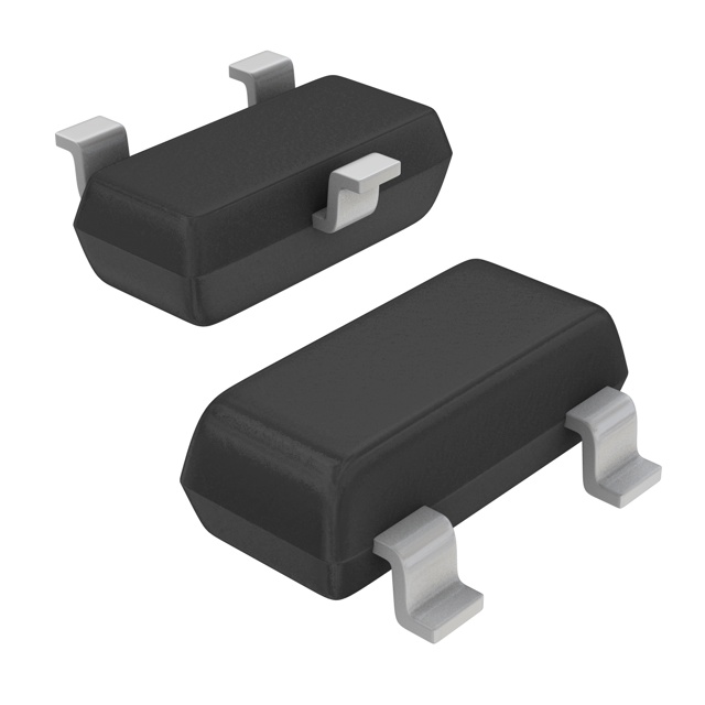
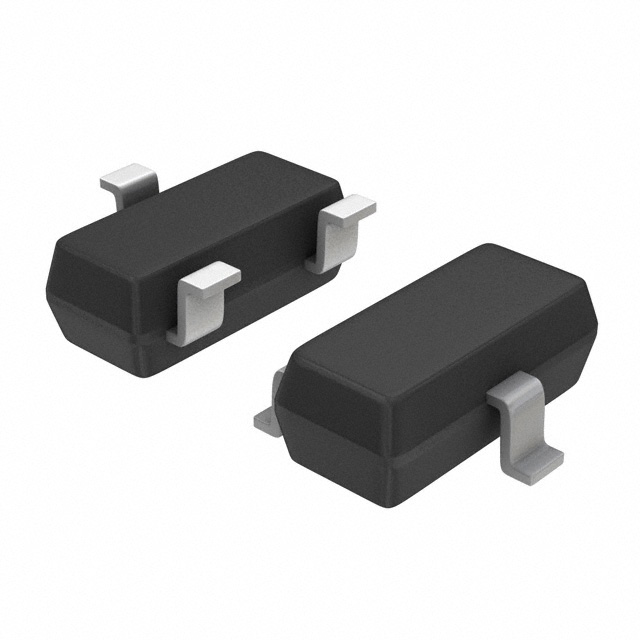
The DDTC115TCA-7-F is a pre-biased NPN bipolar junction transistor (BJT) manufactured by Diodes Incorporated. This surface mount device operates at 50 V maximum collector-emitter breakdown voltage with a maximum collector current of 100 mA and 250 MHz transition frequency. The part is housed in a SOT-23-3 package and is designed for applications requiring integrated base bias resistor networks. The device is Active status and RoHS3 compliant with unlimited moisture sensitivity level (MSL 1).
Substitute parts are necessary when the primary part experiences supply constraints, extended lead times, or when design flexibility across multiple manufacturers is required. Equivalent devices must maintain electrical compatibility across critical parameters including voltage ratings, current ratings, base resistor configurations, and package specifications.
Substiute Parts
Key Parameters
| Parameter | Value | Unit |
|---|---|---|
| Transistor Type | NPN - Pre-Biased | — |
| Voltage - Collector Emitter Breakdown (Max) | 50 | V |
| Current - Collector (Ic) (Max) | 100 | mA |
| Resistor - Base (R1) | 100 | kOhms |
| DC Current Gain (hFE) (Min) @ Ic, Vce | 100 @ 1mA, 5V | — |
| Vce Saturation (Max) @ Ib, Ic | 300mV @ 100µA, 1mA | — |
| Frequency - Transition | 250 | MHz |
| Power - Max | 200 | mW |
| Package / Case | TO-236-3, SC-59, SOT-23-3 | — |
| Mounting Type | Surface Mount | — |
| RoHS Status | ROHS3 Compliant | — |
| Moisture Sensitivity Level (MSL) | 1 (Unlimited) | — |
Substitute Part Grouping Explanation
Substitution of the DDTC115TCA-7-F is determined by strict equivalence across the following critical parameters:
Primary Substitution Criteria:
- Voltage - Collector Emitter Breakdown: 50 V (maximum)
- Current - Collector (Ic): 100 mA (maximum)
- Package / Case: TO-236-3, SC-59, SOT-23-3 (surface mount)
- Mounting Type: Surface Mount
- Transistor Type: NPN - Pre-Biased
- RoHS Status: ROHS3 Compliant
- Moisture Sensitivity Level: 1 (Unlimited)
Secondary Compatibility Parameters:
- Resistor - Base (R1): 100 kOhms (primary configuration)
- DC Current Gain (hFE): 100 @ 1mA, 5V (minimum)
- Frequency - Transition: 250 MHz (minimum)
- Power - Max: 200 mW (minimum)
Substitute parts are grouped into two categories:
Category A - Direct Electrical Equivalents: Parts with identical base resistor configuration (R1 = 100 kOhms) and matching DC current gain specifications. These parts provide pin-for-pin compatibility with no circuit modifications required.
Category B - Functional Equivalents with Modified Bias Networks: Parts with different base resistor configurations (R1 values ranging from 2.2 kOhms to 47 kOhms) or different emitter-base resistor (R2) values. These parts maintain voltage and current ratings but alter the bias point and switching characteristics. Selection requires circuit analysis to confirm compatibility with the intended application.
Parameter Comparison
| Manufacturer Part Number | Manufacturer | Ic (Max) mA | Vce Breakdown (Max) V | R1 (Base) kOhms | hFE (Min) @ Ic, Vce | Vce Sat (Max) mV | Freq - Transition MHz | Power (Max) mW | Package |
|---|---|---|---|---|---|---|---|---|---|
| DDTC115TCA-7-F | Diodes Incorporated | 100 | 50 | 100 | 100 @ 1mA, 5V | 300 @ 100µA, 1mA | 250 | 200 | SOT-23-3 |
| MMUN2241LT1G | onsemi | 100 | 50 | 100 | 160 @ 5mA, 10V | 250 @ 5mA, 10mA | — | 246 | SOT-23-3 |
| PDTC115TT,215 | Nexperia USA Inc. | 100 | 50 | 100 | 100 @ 1mA, 5V | 150 @ 250µA, 5mA | — | 250 | SOT-23-3 |
| DTC114TKAT146 | Rohm Semiconductor | 100 | 50 | 10 | 100 @ 1mA, 5V | 300 @ 1mA, 10mA | 250 | 200 | SOT-23-3 |
| DTC123EKAT146 | Rohm Semiconductor | 100 | 50 | 2.2 | 20 @ 20mA, 5V | 300 @ 500µA, 10mA | 250 | 200 | SOT-23-3 |
| DTC123JKAT146 | Rohm Semiconductor | 100 | 50 | 2.2 | 80 @ 10mA, 5V | 300 @ 250µA, 5mA | 250 | 200 | SOT-23-3 |
| DTC123YKAT146 | Rohm Semiconductor | 100 | 50 | 2.2 | 33 @ 10mA, 5V | 300 @ 500µA, 10mA | 250 | 200 | SOT-23-3 |
| DTC143TKAT146 | Rohm Semiconductor | 100 | 50 | 4.7 | 100 @ 1mA, 5V | 150 @ 250µA, 5mA | 250 | 200 | SOT-23-3 |
| DTC144EKAT146 | Rohm Semiconductor | 100 | 50 | 47 | 68 @ 5mA, 5V | 300 @ 500µA, 10mA | 250 | 200 | SOT-23-3 |
| DTD114GKT146 | Rohm Semiconductor | 500 | 50 | — | 56 @ 50mA, 5V | 300 @ 2.5mA, 50mA | 200 | 200 | SOT-23-3 |
| MMUN2213LT1G | onsemi | 100 | 50 | 47 | 80 @ 5mA, 10V | 250 @ 300µA, 10mA | — | 246 | SOT-23-3 |
Engineering Selection Recommendations
Direct Substitutes (Category A - No Circuit Modification Required):
The PDTC115TT,215 (Nexperia USA Inc.) is the primary direct substitute. This part maintains identical base resistor configuration (R1 = 100 kOhms), matching DC current gain specification (100 @ 1mA, 5V), and equivalent voltage/current ratings. The device is Active status, RoHS3 compliant, and MSL 1 rated. Vce saturation is improved (150 mV vs. 300 mV), indicating superior switching performance. This part is suitable for direct replacement in existing designs without circuit analysis.
The MMUN2241LT1G (onsemi) maintains the 100 kOhms base resistor configuration and 50 V / 100 mA ratings. DC current gain is higher (160 @ 5mA, 10V), and Vce saturation is lower (250 mV). The device is Active status and RoHS3 compliant. This part is suitable for direct replacement where higher current gain is acceptable.
Functional Equivalents (Category B - Circuit Analysis Required):
The DTC143TKAT146 (Rohm Semiconductor) provides a reduced base resistor value (R1 = 4.7 kOhms) with matching DC current gain (100 @ 1mA, 5V) and improved Vce saturation (150 mV). This configuration increases base current drive and reduces switching time. Selection requires confirmation that the application circuit can tolerate increased base current draw.
The DTC114TKAT146 (Rohm Semiconductor) features a significantly reduced base resistor (R1 = 10 kOhms) with matching DC current gain and identical Vce saturation. This part is suitable for applications requiring faster switching response or higher base current availability.
The DTC123 series (DTC123JKAT146, DTC123EKAT146, DTC123YKAT146) employ very low base resistor values (R1 = 2.2 kOhms) with varying emitter-base resistor (R2) configurations. These parts produce different DC current gain characteristics (20 to 80 @ specified conditions) and are intended for applications with specific bias point requirements. Selection from this series requires detailed circuit analysis.
The DTC144EKAT146 (Rohm Semiconductor) features a high base resistor value (R1 = 47 kOhms) with reduced DC current gain (68 @ 5mA, 5V). This configuration reduces base current draw and is suitable for low-power applications or where base current minimization is required.
The DTD114GKT146 (Rohm Semiconductor) is not a direct substitute. This part features a maximum collector current of 500 mA (vs. 100 mA) and is intended for higher current applications. Selection of this part requires confirmation that the application circuit can accommodate the increased current capability.
The MMUN2213LT1G (onsemi) features a high base resistor value (R1 = 47 kOhms) with DC current gain of 80 @ 5mA, 10V. This configuration is suitable for low-power applications where base current minimization is required.
All substitute parts listed are Active status, RoHS3 compliant, and MSL 1 rated, confirming regulatory and environmental compliance equivalence to the primary part.
Frequently Asked Questions (FAQ)
Q: Can PDTC115TT,215 be used as a direct replacement for DDTC115TCA-7-F without circuit modifications?
A: Yes. The PDTC115TT,215 maintains identical base resistor configuration (R1 = 100 kOhms), matching DC current gain specification (100 @ 1mA, 5V), and equivalent voltage/current ratings (50 V, 100 mA). The part is pin-compatible in SOT-23-3 packaging. Vce saturation is improved (150 mV vs. 300 mV), indicating superior switching performance. No circuit modifications are required.
Q: What is the difference between parts with different base resistor values (R1)?
A: The base resistor (R1) determines the bias point and base current drive of the pre-biased transistor. Lower R1 values (2.2 kOhms to 10 kOhms) increase base current availability and reduce switching time, suitable for applications requiring faster response. Higher R1 values (47 kOhms to 100 kOhms) reduce base current draw, suitable for low-power applications. Selection depends on the specific application requirements for switching speed and power consumption.
Q: Are all substitute parts available in the same package as DDTC115TCA-7-F?
A: Yes. All substitute parts listed are available in SOT-23-3 packaging (also designated TO-236-3 or SC-59). This ensures mechanical and electrical compatibility with existing PCB layouts and solder reflow processes.
Q: What does "pre-biased" mean in the context of these transistors?
A: Pre-biased transistors integrate internal resistor networks that establish a fixed bias point without requiring external bias resistors. The DDTC115TCA-7-F includes a 100 kOhms base resistor (R1) that biases the transistor for switching applications. Different pre-biased variants employ different resistor configurations to achieve different bias characteristics.
Q: Can DTC123JKAT146 be substituted for DDTC115TCA-7-F?
A: DTC123JKAT146 is a functional equivalent but not a direct substitute. This part features a significantly lower base resistor (R1 = 2.2 kOhms vs. 100 kOhms) and different DC current gain (80 @ 10mA, 5V vs. 100 @ 1mA, 5V). Substitution requires circuit analysis to confirm that the altered bias point and increased base current drive are compatible with the application. The part maintains 50 V / 100 mA ratings and SOT-23-3 packaging.
Q: What is the significance of DC Current Gain (hFE) specifications?
A: DC current gain (hFE) defines the ratio of collector current to base current at specified operating conditions. Higher hFE values indicate greater current amplification. The DDTC115TCA-7-F specifies hFE of 100 @ 1mA, 5V. Substitute parts with different hFE values will exhibit different switching characteristics and base current requirements. Selection must confirm that the substitute part's hFE is compatible with the application circuit design.
Q: Are all substitute parts RoHS3 compliant?
A: Yes. All substitute parts listed are RoHS3 compliant and MSL 1 rated, confirming regulatory and environmental compliance equivalence to the primary DDTC115TCA-7-F part.
Q: What does Vce Saturation represent?
A: Vce saturation is the minimum collector-emitter voltage when the transistor is fully conducting (saturated). Lower Vce saturation values indicate better switching performance and reduced power dissipation in the saturated state. The DDTC115TCA-7-F specifies 300 mV maximum saturation voltage. Substitute parts with lower saturation voltages (such as PDTC115TT,215 at 150 mV) provide improved efficiency.
Q: Can DTD114GKT146 be used in place of DDTC115TCA-7-F?
A: DTD114GKT146 is not a suitable substitute. While this part maintains the 50 V voltage rating and SOT-23-3 package, it features a maximum collector current of 500 mA (vs. 100 mA for DDTC115TCA-7-F). This higher current capability may cause circuit malfunction if the application is designed for 100 mA maximum operation. Substitution is not recommended without detailed circuit analysis and potential design modifications.
Q: What inventory considerations should guide substitute part selection?
A: Inventory availability varies significantly among substitute parts. DTC143TKAT146 has the highest inventory (365,200 pcs), while DTC123YKAT146 has lower availability (3,100 pcs). For applications requiring immediate availability, DTC143TKAT146 or DTC144EKAT146 are preferred. For long-term supply security, multiple qualified substitutes should be evaluated and approved in the design documentation.
Alternative Parts

SJ6012L2TP
Littelfuse Inc.
6 Alternative Parts

JMK107BBJ476MA-RE
Taiyo Yuden
10 Alternative Parts

GMK107BBJ475MA-T
Taiyo Yuden
5 Alternative Parts
SJ6020N2ARP
Littelfuse Inc.
3 Alternative Parts
SJ6025R2ATP
Littelfuse Inc.
4 Alternative Parts

2474-05L
API Delevan Inc.
1 Alternative Parts

4590R-684K
API Delevan Inc.
1 Alternative Parts

CM6560R-334
API Delevan Inc.
1 Alternative Parts

CM6460-104
API Delevan Inc.
1 Alternative Parts

5526-12
API Delevan Inc.
1 Alternative Parts