


Request Quote
(Ships tomorrow)
DDC115EU-7-F Equivalent & Substitute Parts
Part Overview
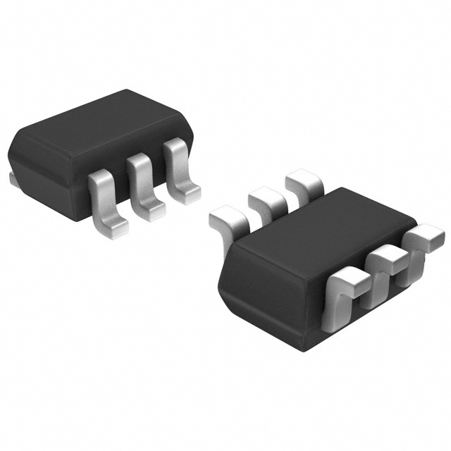
The DDC115EU-7-F is a pre-biased dual NPN bipolar transistor (BJT) manufactured by Diodes Incorporated in a surface mount SOT-363 package. This component integrates two NPN transistors with internal biasing resistors, designed for applications requiring compact switching and amplification functionality. The part is currently in active production status with 4100 units available in inventory.
Substitute parts become necessary when the primary component experiences supply constraints, extended lead times, or when design requirements permit alternative configurations that maintain electrical and mechanical compatibility within specified parameters.
Substiute Parts
Key Parameters
| Parameter | Value | Unit |
|---|---|---|
| Transistor Type | 2 NPN - Pre-Biased (Dual) | — |
| Maximum Collector Current (Ic) | 100 | mA |
| Collector-Emitter Breakdown Voltage (Max) | 50 | V |
| Base Resistor (R1) | 100 | kOhms |
| Emitter-Base Resistor (R2) | 100 | kOhms |
| DC Current Gain (hFE Min) | 82 | @ 5mA, 5V |
| Vce Saturation (Max) | 300 | mV @ 500µA, 10mA |
| Transition Frequency | 250 | MHz |
| Maximum Power Dissipation | 200 | mW |
| Package Type | SOT-363 (6-TSSOP) | — |
| Mounting Type | Surface Mount | — |
| RoHS Status | ROHS3 Compliant | — |
| Moisture Sensitivity Level | 1 (Unlimited) | — |
Substitute Part Grouping Explanation
Substitution eligibility for the DDC115EU-7-F is determined by the following critical parameters:
Electrical Compatibility Requirements:
- Maximum collector current of 100mA or greater
- Collector-emitter breakdown voltage of 50V or greater
- Surface mount package compatible with SOT-363 footprint
- Pre-biased configuration with internal resistor networks
- RoHS3 compliance and MSL 1 rating
Configuration Considerations: The DDC115EU-7-F contains two NPN transistors. Substitute parts may contain alternative transistor configurations (such as 1 NPN and 1 PNP) provided that the electrical parameters remain within or exceed the specified limits for the active transistor(s) used in the application circuit.
Parameter Variance Tolerance: Substitutes are grouped based on matching or exceeding the primary electrical specifications. Variations in transition frequency, DC current gain, and saturation voltage are acceptable when the substitute part maintains functional equivalence within the application's operating range.
Parameter Comparison
| Parameter | DDC115EU-7-F (Diodes) | MUN5336DW1T1G (onsemi) | BCR10PNH6327XTSA1 (Infineon) |
|---|---|---|---|
| Manufacturer | Diodes Incorporated | onsemi | Infineon Technologies |
| Transistor Type | 2 NPN - Pre-Biased | 1 NPN, 1 PNP - Pre-Biased | 1 NPN, 1 PNP - Pre-Biased |
| Maximum Ic (mA) | 100 | 100 | 100 |
| Vce Breakdown (V) | 50 | 50 | 50 |
| Base Resistor R1 (kOhms) | 100 | 100 | 10 |
| Emitter-Base Resistor R2 (kOhms) | 100 | 100 | 10 |
| DC Current Gain (hFE Min) | 82 @ 5mA, 5V | 80 @ 5mA, 10V | 30 @ 5mA, 5V |
| Vce Saturation Max (mV) | 300 @ 500µA, 10mA | 250 @ 300µA, 10mA | 300 @ 500µA, 10mA |
| Transition Frequency (MHz) | 250 | Not specified | 130 |
| Maximum Power (mW) | 200 | 250 | 250 |
| Package | SOT-363 | SC-88/SC70-6/SOT-363 | PG-SOT363-PO |
| Mounting Type | Surface Mount (TR) | Surface Mount (TR) | Surface Mount (CT) |
| Product Status | Active | Active | Last Time Buy |
| RoHS Status | ROHS3 Compliant | ROHS3 Compliant | ROHS3 Compliant |
| MSL Rating | 1 (Unlimited) | 1 (Unlimited) | 1 (Unlimited) |
Engineering Selection Recommendations
MUN5336DW1T1G (onsemi) - Primary Substitute
The MUN5336DW1T1G is the preferred substitute for the DDC115EU-7-F. This part maintains electrical equivalence across all critical parameters: 100mA maximum collector current, 50V breakdown voltage, and matching 100kOhm internal resistor values. The component is in active production status with 6636 units in inventory, ensuring supply continuity. Both parts are ROHS3 compliant with MSL 1 ratings. The MUN5336DW1T1G features a 1 NPN, 1 PNP configuration, which provides functional flexibility for applications requiring complementary transistor pairs while maintaining compatibility with circuits designed for the dual NPN configuration.
BCR10PNH6327XTSA1 (Infineon) - Secondary Substitute
The BCR10PNH6327XTSA1 is a functional substitute with the following considerations: it maintains the 100mA collector current and 50V breakdown voltage specifications. However, this part features 10kOhm internal resistors compared to the 100kOhm values in the primary part, resulting in different biasing characteristics and a lower DC current gain (30 vs. 82). The transition frequency is 130MHz, lower than the DDC115EU-7-F specification of 250MHz. The product status is listed as Last Time Buy, indicating limited future availability. This substitute is suitable only for applications where the lower biasing resistor values and reduced frequency response are compatible with circuit requirements.
Compliance and Certification
All three parts maintain ROHS3 compliance and MSL 1 ratings, ensuring compatibility with standard surface mount assembly processes and storage requirements. All parts are classified under ECCN EAR99 for export control purposes.
Frequently Asked Questions (FAQ)
Q: Can the MUN5336DW1T1G replace the DDC115EU-7-F in existing circuit designs?
A: Yes. The MUN5336DW1T1G maintains electrical equivalence in maximum collector current (100mA), breakdown voltage (50V), and internal resistor values (100kOhms). The primary difference is the transistor configuration: MUN5336DW1T1G contains 1 NPN and 1 PNP transistor, while DDC115EU-7-F contains 2 NPN transistors. Substitution is valid when the circuit design uses only the NPN transistor(s) or when the complementary PNP transistor provides functional benefit.
Q: What are the key differences between the DDC115EU-7-F and BCR10PNH6327XTSA1?
A: The BCR10PNH6327XTSA1 differs in three significant parameters: (1) internal resistor values are 10kOhms versus 100kOhms, affecting biasing behavior; (2) DC current gain is 30 versus 82, resulting in different switching characteristics; (3) transition frequency is 130MHz versus 250MHz. These differences make the BCR10PNH6327XTSA1 suitable only for applications where lower biasing impedance and reduced frequency response are acceptable.
Q: Are all substitute parts available in the same package?
A: All three parts use SOT-363 package variants compatible with the same PCB footprint. The DDC115EU-7-F and MUN5336DW1T1G are supplied in Tape & Reel (TR) packaging, while the BCR10PNH6327XTSA1 is supplied in Cut Tape (CT) packaging. Both packaging formats are compatible with standard surface mount assembly equipment.
Q: What is the significance of the "Last Time Buy" status for the BCR10PNH6327XTSA1?
A: Last Time Buy status indicates that Infineon has announced the end of production for this component. While 9100 units are currently in inventory, future availability is limited. This status makes the BCR10PNH6327XTSA1 a secondary substitute option; the MUN5336DW1T1G is preferred due to its active production status.
Q: Do all substitute parts meet the same compliance requirements?
A: Yes. All three parts are ROHS3 compliant, have MSL 1 (Unlimited) moisture sensitivity ratings, and are classified as REACH Unaffected. All parts are suitable for applications requiring standard environmental and regulatory compliance.
Q: Can the BCR10PNH6327XTSA1 be used in high-frequency applications?
A: The BCR10PNH6327XTSA1 has a transition frequency of 130MHz, compared to 250MHz for the DDC115EU-7-F. Applications requiring operation above 130MHz should use the primary part or MUN5336DW1T1G. The lower frequency specification of the BCR10PNH6327XTSA1 limits its use in high-speed switching circuits.
Q: What is the impact of different internal resistor values on circuit performance?
A: Internal resistor values determine the biasing current and switching speed of pre-biased transistors. The DDC115EU-7-F and MUN5336DW1T1G both use 100kOhm resistors, providing identical biasing behavior. The BCR10PNH6327XTSA1 uses 10kOhm resistors, resulting in 10 times higher biasing current. This affects turn-on/turn-off times and power dissipation. Substitution with different resistor values requires circuit analysis to confirm compatibility.
Alternative Parts

SJ6012L2TP
Littelfuse Inc.
6 Alternative Parts

JMK107BBJ476MA-RE
Taiyo Yuden
10 Alternative Parts

GMK107BBJ475MA-T
Taiyo Yuden
5 Alternative Parts
SJ6020N2ARP
Littelfuse Inc.
3 Alternative Parts
SJ6025R2ATP
Littelfuse Inc.
4 Alternative Parts

2474-05L
API Delevan Inc.
1 Alternative Parts

4590R-684K
API Delevan Inc.
1 Alternative Parts

CM6560R-334
API Delevan Inc.
1 Alternative Parts

CM6460-104
API Delevan Inc.
1 Alternative Parts

5526-12
API Delevan Inc.
1 Alternative Parts