


Request Quote
(Ships tomorrow)
D44H11FP Equivalent & Substitute Parts
Part Overview
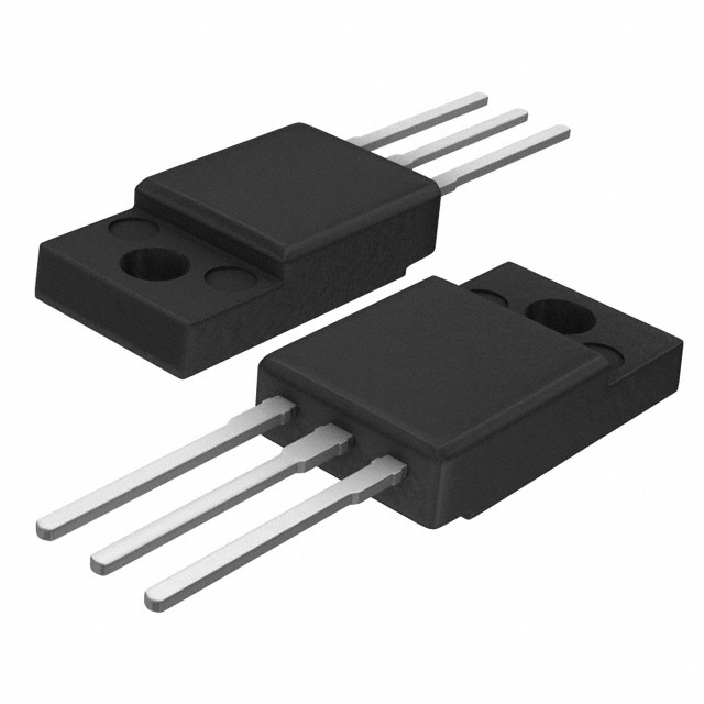
The D44H11FP is an NPN bipolar junction transistor manufactured by STMicroelectronics, housed in a TO-220-3 Full Pack through-hole package. This device is rated for 80 V collector-emitter breakdown voltage and 10 A maximum collector current, with a maximum power dissipation of 36 W. The D44H11FP is classified as obsolete, necessitating identification of active equivalent parts for new designs and ongoing production requirements. Substitute parts must maintain electrical compatibility across critical parameters including voltage rating, current capacity, and saturation characteristics while accommodating packaging and thermal specifications.
Substiute Parts
Key Parameters
| Parameter | Value | Unit |
|---|---|---|
| Transistor Type | NPN | — |
| Voltage - Collector Emitter Breakdown (Max) | 80 | V |
| Current - Collector (Ic) (Max) | 10 | A |
| Power - Max | 36 | W |
| Vce Saturation (Max) @ Ib, Ic | 1V @ 400mA, 8A | — |
| DC Current Gain (hFE) (Min) @ Ic, Vce | 40 @ 4A, 1V | — |
| Current - Collector Cutoff (Max) | 10 | µA |
| Operating Temperature (TJ) | 150 | °C |
| Package / Case | TO-220-3 Full Pack | — |
| Mounting Type | Through Hole | — |
| RoHS Status | ROHS3 Compliant | — |
Substitute Part Grouping Explanation
Substitution eligibility for the D44H11FP is determined by strict adherence to the following electrical and mechanical parameters:
Primary Substitution Criteria:
- Transistor type must be NPN
- Collector-emitter breakdown voltage must be greater than or equal to 80 V
- Maximum collector current must be greater than or equal to 10 A
- Vce saturation characteristics must support the specified operating point
- DC current gain (hFE) must meet or exceed the minimum specification at the defined test conditions
- Package must be TO-220-3 Full Pack through-hole configuration
- RoHS3 compliance required
Substitute Parts Identified:
MJF44H11G (onsemi): Direct electrical equivalent with identical voltage and current ratings. Maintains NPN configuration, 80 V breakdown voltage, and 10 A collector current capacity. Vce saturation and DC current gain specifications match the D44H11FP. Active product status ensures ongoing availability. TO-220-3 Full Pack package maintains mechanical compatibility.
MJF3055G (onsemi): Similar substitute with elevated voltage rating (90 V) and equivalent current capacity (10 A). Maintains NPN configuration and TO-220-3 Full Pack package. Vce saturation specification differs (2.5V @ 3.3A, 10A versus 1V @ 400mA, 8A), and DC current gain is lower (20 @ 4A, 4V). Active product status supports long-term availability.
Parameter Comparison
| Parameter | D44H11FP (STMicroelectronics) | MJF44H11G (onsemi) | MJF3055G (onsemi) |
|---|---|---|---|
| Transistor Type | NPN | NPN | NPN |
| Voltage - Collector Emitter Breakdown (Max) | 80 V | 80 V | 90 V |
| Current - Collector (Ic) (Max) | 10 A | 10 A | 10 A |
| Power - Max | 36 W | 2 W | 2 W |
| Vce Saturation (Max) @ Ib, Ic | 1V @ 400mA, 8A | 1V @ 400mA, 8A | 2.5V @ 3.3A, 10A |
| Current - Collector Cutoff (Max) | 10 µA | 1 µA | 1 µA |
| DC Current Gain (hFE) (Min) @ Ic, Vce | 40 @ 4A, 1V | 40 @ 4A, 1V | 20 @ 4A, 4V |
| Operating Temperature (TJ) | 150°C | -55°C ~ 150°C | -55°C ~ 150°C |
| Package / Case | TO-220-3 Full Pack | TO-220-3 Full Pack | TO-220-3 Full Pack |
| Mounting Type | Through Hole | Through Hole | Through Hole |
| Product Status | Obsolete | Active | Active |
| RoHS Status | ROHS3 Compliant | ROHS3 Compliant | ROHS3 Compliant |
Engineering Selection Recommendations
MJF44H11G Selection Criteria:
The MJF44H11G represents the primary substitute for the obsolete D44H11FP. This part maintains identical electrical specifications across voltage rating (80 V), collector current (10 A), Vce saturation (1V @ 400mA, 8A), and DC current gain (40 @ 4A, 1V). Active product status from onsemi ensures long-term availability and supply chain continuity. RoHS3 compliance and REACH unaffected status align with regulatory requirements. The TO-220-3 Full Pack package provides direct mechanical compatibility with existing PCB layouts and thermal management designs. This substitute is suitable for direct replacement in applications where the D44H11FP was originally specified.
MJF3055G Selection Criteria:
The MJF3055G serves as an alternative substitute when elevated voltage margin is required. The 90 V collector-emitter breakdown voltage provides 10 V additional headroom compared to the D44H11FP specification. Collector current capacity remains at 10 A, maintaining current handling equivalence. Active product status and RoHS3 compliance support regulatory and supply requirements. However, the MJF3055G exhibits higher Vce saturation (2.5V @ 3.3A, 10A) and lower DC current gain (20 @ 4A, 4V) compared to the D44H11FP. These differences require circuit-level evaluation to confirm compatibility with existing bias networks and switching characteristics. The TO-220-3 Full Pack package maintains mechanical compatibility. Selection of this part is appropriate for applications where voltage margin enhancement justifies the modified saturation and gain characteristics.
Power Dissipation Consideration:
Both substitute parts specify maximum power dissipation of 2 W, compared to the D44H11FP rating of 36 W. This represents a significant reduction in thermal capacity. Applications requiring sustained power dissipation above 2 W necessitate enhanced thermal management through increased heatsink area, improved thermal coupling, or circuit redesign to reduce average power consumption.
Frequently Asked Questions (FAQ)
Q: Can the MJF44H11G directly replace the D44H11FP without circuit modification?
A: The MJF44H11G maintains identical electrical specifications for voltage rating, collector current, Vce saturation, and DC current gain at the specified test conditions. Direct replacement is supported from an electrical standpoint. However, the reduced maximum power dissipation (2 W versus 36 W) requires thermal management evaluation. If the original application dissipates power below 2 W, direct replacement is feasible. Applications exceeding 2 W power dissipation require enhanced heatsinking or circuit redesign.
Q: What are the key differences between MJF44H11G and MJF3055G?
A: The MJF44H11G and MJF3055G differ in three primary parameters. The MJF3055G provides higher collector-emitter breakdown voltage (90 V versus 80 V), offering increased voltage margin. The MJF3055G exhibits higher Vce saturation (2.5V @ 3.3A, 10A versus 1V @ 400mA, 8A) and lower DC current gain (20 @ 4A, 4V versus 40 @ 4A, 1V). These differences affect switching speed, base drive requirements, and saturation losses. Selection depends on whether the application prioritizes voltage margin or maintains the original saturation and gain characteristics.
Q: Are both substitute parts available in the same packaging as the D44H11FP?
A: Yes. Both MJF44H11G and MJF3055G are supplied in TO-220-3 Full Pack through-hole packages, identical to the D44H11FP. This packaging compatibility ensures mechanical fit with existing PCB layouts, mounting hardware, and thermal interface designs without modification.
Q: What is the significance of the reduced power rating in the substitute parts?
A: The D44H11FP specifies 36 W maximum power dissipation, while both substitute parts specify 2 W. This reduction reflects differences in thermal design and junction-to-case thermal resistance. Applications operating at power levels between 2 W and 36 W require thermal management enhancement through larger heatsinks, improved thermal coupling, or forced-air cooling to maintain junction temperature within the 150°C maximum specification.
Q: Are the substitute parts RoHS3 compliant?
A: Yes. Both MJF44H11G and MJF3055G are RoHS3 compliant and REACH unaffected, matching the regulatory status of the D44H11FP. These certifications support use in applications subject to environmental and hazardous substance restrictions.
Q: What is the operating temperature range for the substitute parts?
A: Both MJF44H11G and MJF3055G specify an operating temperature range of -55°C to 150°C (TJ), compared to the D44H11FP maximum of 150°C. The substitute parts provide extended low-temperature operation capability, supporting applications requiring operation below 0°C.
Q: How do the collector cutoff current specifications differ?
A: The D44H11FP specifies maximum collector cutoff current of 10 µA, while both substitute parts specify 1 µA. The lower cutoff current in the substitute parts indicates reduced leakage current, which may improve circuit performance in applications sensitive to reverse leakage, such as precision switching or low-power standby modes.
Alternative Parts

SJ6012L2TP
Littelfuse Inc.
6 Alternative Parts

JMK107BBJ476MA-RE
Taiyo Yuden
10 Alternative Parts

GMK107BBJ475MA-T
Taiyo Yuden
5 Alternative Parts
SJ6020N2ARP
Littelfuse Inc.
3 Alternative Parts
SJ6025R2ATP
Littelfuse Inc.
4 Alternative Parts

2474-05L
API Delevan Inc.
1 Alternative Parts

4590R-684K
API Delevan Inc.
1 Alternative Parts

CM6560R-334
API Delevan Inc.
1 Alternative Parts

CM6460-104
API Delevan Inc.
1 Alternative Parts

5526-12
API Delevan Inc.
1 Alternative Parts