


Request Quote
(Ships tomorrow)
CS23-12IO2 Equivalent & Substitute Parts
Part Overview
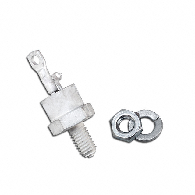
The CS23-12IO2 is a 1.2 kV, 50 A SCR (Silicon Controlled Rectifier) in TO-208AA stud mount packaging manufactured by IXYS. This component is classified as obsolete, making substitute parts necessary for new designs and ongoing production requirements. The part operates across a temperature range of -40°C to 125°C and is ROHS3 compliant. Due to its obsolete status, equivalent alternatives with active product status are available to maintain design continuity and supply chain reliability.
Substiute Parts
Key Parameters
| Parameter | CS23-12IO2 |
|---|---|
| Voltage - Off State | 1.2 kV |
| Voltage - Gate Trigger (Vgt) (Max) | 2.5 V |
| Current - Gate Trigger (Igt) (Max) | 50 mA |
| Voltage - On State (Vtm) (Max) | 1.8 V |
| Current - On State (It (RMS)) (Max) | 50 A |
| Current - Hold (Ih) (Max) | 100 mA |
| Current - Off State (Max) | 3 mA |
| Operating Temperature | -40°C ~ 125°C |
| Mounting Type | Chassis, Stud Mount |
| Package / Case | TO-208AA (TO-48) |
| SCR Type | Standard Recovery |
| Product Status | Obsolete |
Substitute Part Grouping Explanation
Substitution for the CS23-12IO2 is determined by the following critical parameters: off-state voltage rating (1.2 kV), SCR type (Standard Recovery), and RMS current capability. All substitute parts maintain the 1.2 kV voltage class and Standard Recovery characteristics. The substitutes are grouped into two categories based on mounting and packaging approach:
Category 1: Direct Voltage and Current Class Match (CLA50E1200HB) This part maintains the 1.2 kV rating with higher RMS current capacity (79 A vs. 50 A) and improved thermal performance through TO-247AD through-hole packaging. Gate trigger voltage is lower (1.5 V vs. 2.5 V), reducing gate drive requirements.
Category 2: Module-Based Alternatives (MCO50-12IO1, MCO25-12IO1) These SCR modules provide 1.2 kV ratings in SOT-227-4 miniBLOC chassis mount packaging. MCO50-12IO1 offers 85 A RMS current with lower gate trigger voltage (1.4 V). MCO25-12IO1 provides 49 A RMS current with 1.5 V gate trigger voltage. Both support higher operating temperatures (-40°C to 150°C).
Parameter Comparison
| Parameter | CS23-12IO2 | CLA50E1200HB | MCO50-12IO1 | MCO25-12IO1 |
|---|---|---|---|---|
| Voltage - Off State | 1.2 kV | 1.2 kV | 1.2 kV | 1.2 kV |
| Voltage - Gate Trigger (Vgt) (Max) | 2.5 V | 1.5 V | 1.4 V | 1.5 V |
| Current - Gate Trigger (Igt) (Max) | 50 mA | 50 mA | 80 mA | 55 mA |
| Voltage - On State (Vtm) (Max) | 1.8 V | 1.6 V | — | — |
| Current - On State (It (RMS)) (Max) | 50 A | 79 A | 85 A | 49 A |
| Current - Hold (Ih) (Max) | 100 mA | 75 mA | 100 mA | 100 mA |
| Operating Temperature | -40°C ~ 125°C | -40°C ~ 150°C | -40°C ~ 150°C | -40°C ~ 150°C |
| SCR Type | Standard Recovery | Standard Recovery | Standard Recovery | Standard Recovery |
| Mounting Type | Chassis, Stud Mount | Through Hole | Chassis Mount | Chassis Mount |
| Package / Case | TO-208AA (TO-48) | TO-247-3 | SOT-227-4, miniBLOC | SOT-227-4, miniBLOC |
| Product Status | Obsolete | Active | Active | Active |
| RoHS Status | ROHS3 Compliant | ROHS3 Compliant | ROHS3 Compliant | ROHS3 Compliant |
Engineering Selection Recommendations
All substitute parts maintain ROHS3 compliance and REACH unaffected status, matching the regulatory requirements of the CS23-12IO2. Selection between substitutes depends on application-specific mounting and thermal requirements:
CLA50E1200HB is suitable for applications requiring through-hole mounting with higher current capacity and improved thermal performance. The lower gate trigger voltage (1.5 V) reduces gate drive circuit complexity compared to the original 2.5 V specification.
MCO50-12IO1 provides the highest RMS current rating (85 A) and lowest gate trigger voltage (1.4 V) in a chassis mount module format. This part is recommended for designs requiring maximum current handling within the 1.2 kV class and extended operating temperature range to 150°C.
MCO25-12IO1 offers a conservative current rating (49 A RMS) closely matching the original CS23-12IO2 specification (50 A RMS) in a chassis mount module format. This part is recommended for direct functional replacement with minimal design modification.
Frequently Asked Questions (FAQ)
Q: Can the CS23-12IO2 be directly replaced with CLA50E1200HB? A: CLA50E1200HB maintains the 1.2 kV voltage rating and Standard Recovery SCR type. However, the mounting method differs: CLA50E1200HB uses through-hole TO-247AD packaging versus the original stud mount TO-208AA. PCB layout and mechanical mounting must be redesigned accordingly. The lower gate trigger voltage (1.5 V vs. 2.5 V) may require gate drive circuit adjustment.
Q: What is the difference between the discrete SCR (CLA50E1200HB) and module alternatives (MCO50-12IO1, MCO25-12IO1)? A: CLA50E1200HB is a discrete SCR component in TO-247AD packaging. MCO50-12IO1 and MCO25-12IO1 are integrated SCR modules in SOT-227-4 miniBLOC packaging with internal gate and cathode connections. Module-based parts may include additional internal protection or integration features not present in discrete components.
Q: Are all substitute parts rated for the same temperature range as the CS23-12IO2? A: No. The CS23-12IO2 operates from -40°C to 125°C. All three substitute parts extend the upper temperature limit to 150°C, providing improved thermal margin for high-temperature applications.
Q: Which substitute part is recommended for new designs? A: MCO50-12IO1 is recommended for new designs requiring active product status, highest current capacity (85 A RMS), lowest gate trigger voltage (1.4 V), and extended temperature range. MCO25-12IO1 is recommended if the original 50 A RMS current specification must be closely matched. CLA50E1200HB is recommended if through-hole mounting is required.
Q: Do all substitute parts have the same RoHS and REACH compliance status? A: Yes. All substitute parts are ROHS3 compliant and REACH unaffected, matching the regulatory status of the CS23-12IO2.
Q: What is the impact of lower gate trigger voltage on circuit design? A: Lower gate trigger voltage (1.4 V to 1.5 V vs. 2.5 V) reduces the gate drive current requirement and may allow use of lower-power gate drive circuits. Existing gate drive designs must be verified for compatibility with the lower voltage threshold to ensure reliable triggering.
Alternative Parts

SJ6012L2TP
Littelfuse Inc.
6 Alternative Parts

JMK107BBJ476MA-RE
Taiyo Yuden
10 Alternative Parts

GMK107BBJ475MA-T
Taiyo Yuden
5 Alternative Parts
SJ6020N2ARP
Littelfuse Inc.
3 Alternative Parts
SJ6025R2ATP
Littelfuse Inc.
4 Alternative Parts

2474-05L
API Delevan Inc.
1 Alternative Parts

4590R-684K
API Delevan Inc.
1 Alternative Parts

CM6560R-334
API Delevan Inc.
1 Alternative Parts

CM6460-104
API Delevan Inc.
1 Alternative Parts

5526-12
API Delevan Inc.
1 Alternative Parts