


Request Quote
(Ships tomorrow)
CPH6444-TL-W N-Channel MOSFET Equivalent & Substitute Parts
Part Overview
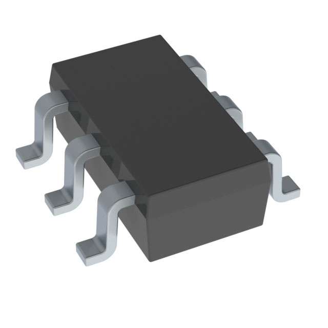
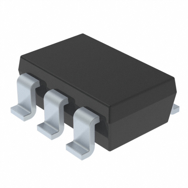
The CPH6444-TL-W is an N-Channel 60V MOSFET manufactured by onsemi, rated for 4.5A continuous drain current in a 6-CPH surface mount package. This device is classified as obsolete, necessitating identification of active equivalent and substitute components for ongoing design requirements and production continuity. Substitute parts must maintain electrical compatibility across voltage ratings, current handling, and thermal characteristics while accommodating potential package variations.
Substiute Parts
Key Parameters
| Parameter | Value | Unit |
|---|---|---|
| FET Type | N-Channel | — |
| Drain to Source Voltage (Vdss) | 60 | V |
| Continuous Drain Current (Id) @ 25°C | 4.5 | A |
| Rds On (Max) @ 10V Vgs | 78 | mOhm |
| Gate Charge (Qg) @ 10V | 10 | nC |
| Power Dissipation (Max) | 1.6 | W |
| Operating Temperature (TJ) | 150 | °C |
| Package Type | SOT-23-6 | — |
| RoHS Status | ROHS3 Compliant | — |
Substitute Part Grouping Explanation
Substitution eligibility for the CPH6444-TL-W is determined by the following critical parameters:
Electrical Compatibility Requirements:
- Drain to Source Voltage (Vdss): Must equal or exceed 60V
- Continuous Drain Current (Id): Must equal or exceed 4.5A at 25°C
- Gate Charge (Qg): Lower values indicate improved switching performance
- Rds On: Lower on-resistance values improve efficiency and reduce thermal dissipation
Thermal & Mechanical Requirements:
- Operating Temperature: Must support minimum 150°C junction temperature
- Package Type: SOT-23-6 or compatible surface mount variants
- Mounting Type: Surface mount configuration required
- Compliance: ROHS3 compliance and MSL Level 1 required
Product Status Consideration:
- Active status preferred for long-term availability and supply chain continuity
- Obsolete status acceptable only for legacy system maintenance
The substitute parts listed below satisfy these criteria with variations in specific parameters that do not compromise functional equivalence within typical application tolerances.
Parameter Comparison
| Parameter | CPH6444-TL-W | FDC5612 | SI3458BDV-T1-E3 | SI3458BDV-T1-GE3 | ZXMN6A08E6TA |
|---|---|---|---|---|---|
| Manufacturer | onsemi | onsemi | Vishay Siliconix | Vishay Siliconix | Diodes Incorporated |
| Product Status | Obsolete | Active | Active | Active | Active |
| Vdss (V) | 60 | 60 | 60 | 60 | 60 |
| Id @ 25°C (A) | 4.5 | 4.3 | 4.1 | 4.1 | 2.8 |
| Rds On @ 10V Vgs (mOhm) | 78 @ 2A | 55 @ 4.3A | 100 @ 3.2A | 100 @ 3.2A | 80 @ 4.8A |
| Qg @ 10V (nC) | 10 | 18 | 11 | 11 | 5.8 |
| Power Dissipation (W) | 1.6 | 1.6 | 2 (Ta) / 3.3 (Tc) | 2 (Ta) / 3.3 (Tc) | 1.1 |
| Operating Temperature (°C) | 150 | -55 to 150 | -55 to 150 | -55 to 150 | -55 to 150 |
| Package | SOT-23-6 | SOT-23-6 Thin / TSOT-23-6 | SOT-23-6 Thin / TSOT-23-6 | SOT-23-6 Thin / TSOT-23-6 | SOT-23-6 |
| RoHS Status | ROHS3 Compliant | ROHS3 Compliant | ROHS3 Compliant | ROHS3 Compliant | ROHS3 Compliant |
| MSL Level | 1 (Unlimited) | 1 (Unlimited) | 1 (Unlimited) | 1 (Unlimited) | 1 (Unlimited) |
Engineering Selection Recommendations
Primary Substitute: FDC5612 (onsemi)
The FDC5612 is the preferred substitute for CPH6444-TL-W applications. Both devices are manufactured by onsemi, ensuring design continuity and supply chain alignment. The FDC5612 maintains identical Vdss (60V) and power dissipation (1.6W) specifications. Current rating of 4.3A is within 95.6% of the original 4.5A specification. The FDC5612 features superior on-resistance (55mOhm vs. 78mOhm), reducing thermal dissipation in high-frequency switching applications. Active product status ensures long-term availability. Package compatibility is confirmed through SOT-23-6 Thin and TSOT-23-6 designations.
Secondary Substitutes: SI3458BDV-T1-E3 and SI3458BDV-T1-GE3 (Vishay Siliconix)
Both SI3458 variants maintain 60V Vdss rating and support 4.1A continuous drain current (91.1% of original specification). These TrenchFET® devices offer enhanced thermal performance with power dissipation up to 3.3W at case temperature. Gate charge of 11nC is comparable to the original 10nC. Active product status and extended operating temperature range (-55°C to 150°C) provide design flexibility. SI3458BDV-T1-GE3 offers higher inventory availability (15,265 units) compared to SI3458BDV-T1-E3 (1,489 units).
Conditional Substitute: ZXMN6A08E6TA (Diodes Incorporated)
The ZXMN6A08E6TA is suitable only for applications where continuous drain current requirements do not exceed 2.8A. This device provides the lowest gate charge (5.8nC), beneficial for high-frequency switching circuits. Reduced power dissipation (1.1W) indicates lower thermal load. Use this substitute only when application current demands are confirmed below 2.8A continuous operation.
Compliance & Certification:
All substitute parts maintain ROHS3 compliance and MSL Level 1 (unlimited moisture sensitivity), matching the original CPH6444-TL-W specifications. All devices carry EAR99 ECCN classification and REACH Unaffected status, ensuring regulatory alignment for international applications.
Frequently Asked Questions (FAQ)
Q: Can the FDC5612 directly replace the CPH6444-TL-W in existing PCB layouts?
A: The FDC5612 uses SOT-23-6 Thin and TSOT-23-6 package designations, which are mechanically compatible with the original 6-CPH package footprint. Pin configuration and lead spacing conform to SOT-23-6 standards. PCB layout compatibility should be confirmed through package outline drawings, as thin variants may have dimensional variations.
Q: What is the significance of the lower gate charge in the ZXMN6A08E6TA?
A: Gate charge (Qg) directly affects switching speed and driver power requirements. The ZXMN6A08E6TA's 5.8nC gate charge (versus 10nC in the original) reduces gate drive energy and enables faster switching transitions. This characteristic is advantageous in high-frequency applications but is only relevant if the application current requirement does not exceed 2.8A.
Q: Are the SI3458 variants interchangeable with each other?
A: SI3458BDV-T1-E3 and SI3458BDV-T1-GE3 are electrically identical. Both feature identical electrical specifications, operating temperature range, and package configuration. The primary difference is inventory availability and packaging format (Tape & Reel). Selection between these variants should be based on supply chain requirements and procurement volume.
Q: Why does the FDC5612 have higher gate charge than the original CPH6444-TL-W?
A: Gate charge of 18nC in the FDC5612 versus 10nC in the original reflects different semiconductor process technology and die design. The FDC5612's PowerTrench® technology prioritizes on-resistance reduction (55mOhm vs. 78mOhm), which inherently increases gate charge. This trade-off results in lower conduction losses and improved thermal efficiency in most applications.
Q: Can I use the ZXMN6A08E6TA in a 4.5A application?
A: No. The ZXMN6A08E6TA is rated for 2.8A continuous drain current. Operating this device at 4.5A exceeds its continuous current specification and will result in excessive junction temperature rise, potential thermal runaway, and device failure. Use this substitute only in applications confirmed to operate below 2.8A.
Q: What is the difference between Ta and Tc temperature ratings?
A: Ta (ambient temperature) refers to the surrounding air temperature, while Tc (case temperature) refers to the device package temperature. The SI3458 variants specify power dissipation at both Ta (2W) and Tc (3.3W), indicating higher thermal performance when case temperature is controlled. The CPH6444-TL-W and FDC5612 specify only Ta-based power dissipation (1.6W).
Q: Are all substitute parts available in the same packaging format?
A: No. The FDC5612 is available in Cut Tape (CT) and Digi-Reel® packaging, while SI3458 variants are supplied in Tape & Reel (TR) format. The ZXMN6A08E6TA is available in Cut Tape (CT) and Digi-Reel® packaging. Packaging format selection depends on procurement volume and assembly line requirements.
Q: Does the extended operating temperature range of substitute parts affect compatibility?
A: The extended operating temperature range (-55°C to 150°C) in substitute parts provides additional design margin compared to the original CPH6444-TL-W (150°C maximum). This does not negatively affect compatibility; it only expands the operational envelope. Applications operating within the original temperature specification remain fully compatible.
Alternative Parts

SJ6012L2TP
Littelfuse Inc.
6 Alternative Parts

JMK107BBJ476MA-RE
Taiyo Yuden
10 Alternative Parts

GMK107BBJ475MA-T
Taiyo Yuden
5 Alternative Parts
SJ6020N2ARP
Littelfuse Inc.
3 Alternative Parts
SJ6025R2ATP
Littelfuse Inc.
4 Alternative Parts

2474-05L
API Delevan Inc.
1 Alternative Parts

4590R-684K
API Delevan Inc.
1 Alternative Parts

CM6560R-334
API Delevan Inc.
1 Alternative Parts

CM6460-104
API Delevan Inc.
1 Alternative Parts

5526-12
API Delevan Inc.
1 Alternative Parts