


Request Quote
(Ships tomorrow)
CLF6045T-151M-H Equivalent & Substitute Parts
Part Overview
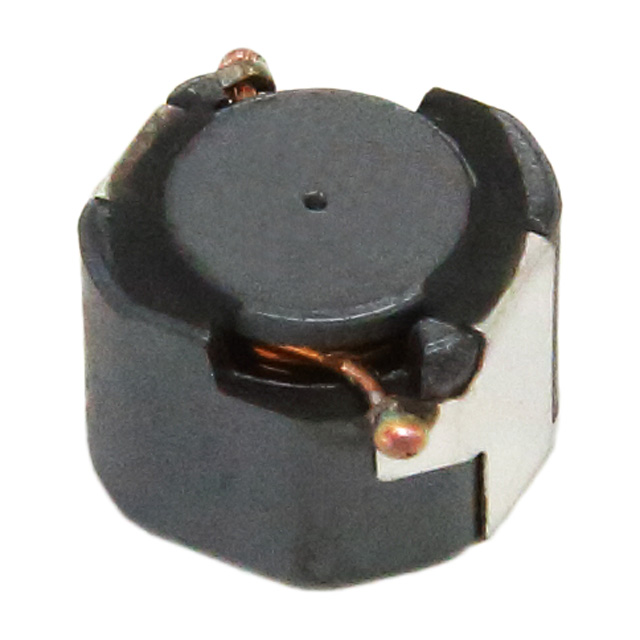
The CLF6045T-151M-H is a 150 µH shielded drum core wirewound inductor manufactured by TDK Corporation, rated for 600 mA continuous current with 480 mOhm DC resistance. This component is classified as Not For New Designs, indicating it has been superseded in TDK's product portfolio. Finding equivalent substitute parts is necessary for applications requiring continued supply, design updates, or component optimization while maintaining electrical and mechanical compatibility.
Substiute Parts
Key Parameters
| Parameter | Value |
|---|---|
| Inductance | 150 µH |
| Inductance Tolerance | ±20% |
| Current Rating | 600 mA |
| DC Resistance (DCR) | 480 mOhm |
| Saturation Current (Isat) | 500 mA |
| Core Material | Ferrite |
| Shielding | Shielded |
| Operating Temperature Range | -40°C to 125°C |
| Mounting Type | Surface Mount |
| Package Type | Nonstandard |
| Test Frequency | 100 kHz |
| RoHS Status | ROHS3 Compliant |
| Moisture Sensitivity Level | 1 (Unlimited) |
Substitute Part Grouping Explanation
Substitute parts for the CLF6045T-151M-H are qualified based on the following electrical and mechanical parameters:
Primary Matching Criteria:
- Inductance value: 150 µH ±20% tolerance
- Core material: Ferrite
- Shielding: Shielded construction
- Mounting type: Surface Mount
- Test frequency: 100 kHz
- RoHS3 compliance
Secondary Compatibility Parameters:
- Current rating capability (minimum 600 mA or higher)
- DC resistance within acceptable operating limits
- Operating temperature range compatibility (-40°C minimum, 125°C maximum)
- Package dimensions and height within mechanical constraints
- Saturation current characteristics
The two identified substitutes meet these criteria with variations in current rating, DC resistance, and physical dimensions that remain within acceptable engineering tolerances for equivalent functionality.
Parameter Comparison
| Parameter | CLF6045T-151M-H (Main) | CLF6045NIT-151M-D (Substitute) | CDRR75NP-151MC (Substitute) |
|---|---|---|---|
| Manufacturer | TDK Corporation | TDK Corporation | Sumida America Components Inc. |
| Inductance | 150 µH | 150 µH | 150 µH |
| Inductance Tolerance | ±20% | ±20% | ±20% |
| Current Rating (Amps) | 600 mA | 530 mA | 660 mA |
| Saturation Current (Isat) | 500 mA | 530 mA | 360 mA |
| DC Resistance (DCR) | 480 mOhm | 576 mOhm Max | 485 mOhm Max |
| Core Material | Ferrite | Ferrite | Ferrite |
| Shielding | Shielded | Shielded | Shielded |
| Operating Temperature Range | -40°C to 125°C | -55°C to 150°C | -40°C to 125°C |
| Mounting Type | Surface Mount | Surface Mount | Surface Mount |
| Length x Width (mm) | 6.20 x 5.90 | 6.30 x 6.00 | 6.90 x 6.90 |
| Height - Seated Max (mm) | 4.50 | 4.80 | 4.80 |
| RoHS Status | ROHS3 Compliant | ROHS3 Compliant | ROHS3 Compliant |
| Moisture Sensitivity Level | 1 (Unlimited) | 1 (Unlimited) | 1 (Unlimited) |
| Product Status | Not For New Designs | Active | Active |
Engineering Selection Recommendations
CLF6045NIT-151M-D (TDK Corporation): This substitute is recommended as the primary alternative for applications requiring continued TDK sourcing. It maintains the same inductance value and tolerance, with an extended operating temperature range (-55°C to 150°C) and AEC-Q200 automotive qualification. The current rating of 530 mA is lower than the original 600 mA specification; applications operating near maximum current limits require verification against actual load profiles. DC resistance increases to 576 mOhm maximum, representing a 20% increase in resistive losses. Physical dimensions are marginally larger (6.30 x 6.00 mm vs. 6.20 x 5.90 mm), with increased height (4.80 mm vs. 4.50 mm). This part is actively manufactured and widely available.
CDRR75NP-151MC (Sumida America Components Inc.): This substitute offers the highest current rating at 660 mA, providing design margin above the original 600 mA specification. DC resistance of 485 mOhm maximum is comparable to the original 480 mOhm. The saturation current of 360 mA is significantly lower than both the original part (500 mA) and the TDK alternative (530 mA), requiring careful evaluation in applications with transient current spikes. Physical dimensions are larger (6.90 x 6.90 mm footprint), which may impact PCB layout compatibility. Operating temperature range matches the original specification (-40°C to 125°C). This part is actively manufactured with moderate inventory availability.
Both substitutes maintain ROHS3 compliance, ferrite core construction, shielded design, and surface mount packaging. Selection between them depends on current rating requirements, saturation current tolerance, physical space constraints, and supplier preference.
Frequently Asked Questions (FAQ)
Q: Can CLF6045NIT-151M-D be used as a direct replacement for CLF6045T-151M-H?
A: CLF6045NIT-151M-D is electrically compatible for most applications. The 530 mA current rating is 70 mA lower than the original 600 mA specification. Applications operating continuously above 530 mA require design review. DC resistance increases from 480 mOhm to 576 mOhm maximum, resulting in approximately 20% higher resistive losses. Physical dimensions are slightly larger; verify PCB layout compatibility before implementation.
Q: What is the significance of the saturation current difference between CDRR75NP-151MC (360 mA) and the original part (500 mA)?
A: Saturation current defines the threshold at which the inductor's inductance begins to degrade under transient current conditions. The CDRR75NP-151MC exhibits saturation 140 mA lower than the original part. Applications with transient current peaks or load step conditions must ensure peak currents remain below 360 mA to maintain inductance stability. Steady-state current rating of 660 mA is independent of saturation current.
Q: Are there physical space constraints when substituting these parts?
A: Yes. The original CLF6045T-151M-H measures 6.20 x 5.90 mm with 4.50 mm height. CLF6045NIT-151M-D increases to 6.30 x 6.00 mm with 4.80 mm height. CDRR75NP-151MC is the largest at 6.90 x 6.90 mm with 4.80 mm height. Verify PCB footprint, trace routing, and component clearance before selecting the larger Sumida part.
Q: Do all three parts meet the same compliance standards?
A: All three parts are ROHS3 compliant with MSL 1 (Unlimited) moisture sensitivity. CLF6045NIT-151M-D includes AEC-Q200 automotive qualification, which the original and Sumida parts do not specify. For automotive or high-reliability applications, CLF6045NIT-151M-D is the preferred choice.
Q: What is the impact of increased DC resistance on circuit performance?
A: DC resistance causes resistive losses proportional to I²R. The CLF6045NIT-151M-D at 576 mOhm maximum represents a 20% increase over the original 480 mOhm. At 600 mA, this results in approximately 0.21 W additional power dissipation compared to 0.17 W for the original part. CDRR75NP-151MC at 485 mOhm maximum is nearly equivalent to the original. Thermal management and efficiency calculations must account for this difference in high-power applications.
Q: Can these parts be used interchangeably in the same circuit?
A: Electrical interchangeability depends on application-specific requirements for current rating, saturation current, DC resistance, and operating temperature. Mechanical interchangeability requires PCB layout verification due to dimensional differences. Conduct circuit simulation and thermal analysis before finalizing substitution decisions.
Alternative Parts

SJ6012L2TP
Littelfuse Inc.
6 Alternative Parts

JMK107BBJ476MA-RE
Taiyo Yuden
10 Alternative Parts

GMK107BBJ475MA-T
Taiyo Yuden
5 Alternative Parts
SJ6020N2ARP
Littelfuse Inc.
3 Alternative Parts
SJ6025R2ATP
Littelfuse Inc.
4 Alternative Parts

2474-05L
API Delevan Inc.
1 Alternative Parts

4590R-684K
API Delevan Inc.
1 Alternative Parts

CM6560R-334
API Delevan Inc.
1 Alternative Parts

CM6460-104
API Delevan Inc.
1 Alternative Parts

5526-12
API Delevan Inc.
1 Alternative Parts