


Request Quote
(Ships tomorrow)
CLF10040T-150M-H Equivalent & Substitute Parts
Part Overview
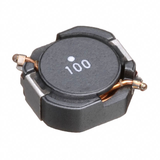
The CLF10040T-150M-H is a 15 µH shielded drum core wirewound inductor manufactured by TDK Corporation, rated for 3.2 A continuous current with 40mOhm DC resistance. This component is classified as Not For New Designs, indicating it has been superseded in TDK's product portfolio. Finding equivalent or substitute parts is necessary for ongoing support of legacy systems, design revisions, or when primary inventory becomes unavailable.
Substiute Parts
Key Parameters
| Parameter | Value |
|---|---|
| Inductance | 15 µH |
| Inductance Tolerance | ±20% |
| Current Rating | 3.2 A |
| Saturation Current (Isat) | 2.5 A |
| DC Resistance (DCR) | 40 mOhm |
| Core Material | Ferrite |
| Shielding | Shielded |
| Operating Temperature Range | -40°C to 125°C |
| Mounting Type | Surface Mount |
| Package Type | Nonstandard |
| Size | 10.00mm L x 9.70mm W x 4.10mm H |
| RoHS Status | ROHS3 Compliant |
| MSL Rating | 1 (Unlimited) |
Substitute Part Grouping Explanation
Substitute parts for the CLF10040T-150M-H are qualified based on the following electrical and mechanical parameters:
Primary Substitution Criteria:
- Inductance value: 15 µH (exact match required)
- Core type: Ferrite shielded drum core wirewound
- Mounting: Surface mount
- Inductance tolerance: ±20% or tighter
- Operating temperature range: Must encompass or exceed -40°C to 125°C
- RoHS3 compliance: Required for regulatory alignment
Secondary Compatibility Factors:
- Current rating: Minimum 3.2 A (higher ratings acceptable for derating applications)
- DC resistance: 40 mOhm or lower (lower DCR preferred for reduced losses)
- Package footprint: Nonstandard dimensions must be verified for PCB layout compatibility
- MSL rating: 1 (Unlimited) preferred for storage and handling consistency
Two substitute parts meet these criteria with varying trade-offs in current capacity, thermal performance, and product lifecycle status.
Parameter Comparison
| Parameter | CLF10040T-150M-H (Main) | CLF10060NIT-150M-D (Substitute 1) | B82559A0153A016 (Substitute 2) |
|---|---|---|---|
| Manufacturer | TDK Corporation | TDK Corporation | EPCOS - TDK Electronics |
| Inductance | 15 µH | 15 µH | 15 µH |
| Inductance Tolerance | ±20% | ±20% | ±10% |
| Current Rating (Amps) | 3.2 A | 3.3 A | 11 A |
| Saturation Current (Isat) | 2.5 A | 3.3 A | 12.6 A |
| DC Resistance (DCR) | 40 mOhm | 36 mOhm Max | 11.1 mOhm Max |
| Core Material | Ferrite | Ferrite | Ferrite |
| Shielding | Shielded | Shielded | Shielded |
| Operating Temperature Range | -40°C to 125°C | -55°C to 150°C | -40°C to 150°C |
| Mounting Type | Surface Mount | Surface Mount | Surface Mount |
| Package Type | Nonstandard | Nonstandard | Nonstandard, 3 Lead |
| Size (L x W x H) | 10.00 x 9.70 x 4.10 mm | 10.10 x 10.00 x 6.30 mm | 18.70 x 17.30 x 9.60 mm |
| Product Status | Not For New Designs | Last Time Buy | Obsolete |
| RoHS Status | ROHS3 Compliant | ROHS3 Compliant | ROHS3 Compliant |
| MSL Rating | 1 (Unlimited) | 1 (Unlimited) | 1 (Unlimited) |
| AEC-Q200 Rated | No | Yes | Yes |
Engineering Selection Recommendations
CLF10060NIT-150M-D (Recommended Primary Substitute)
This part is the closest functional equivalent to the CLF10040T-150M-H. It maintains the same 15 µH inductance value, ferrite shielded drum core construction, and surface mount configuration. The CLF10060NIT-150M-D offers marginal improvements in current rating (3.3 A vs. 3.2 A) and lower DC resistance (36 mOhm Max vs. 40 mOhm), resulting in reduced power dissipation. The extended operating temperature range (-55°C to 150°C) provides additional thermal margin. However, the footprint is slightly larger (10.10 x 10.00 x 6.30 mm vs. 10.00 x 9.70 x 4.10 mm), requiring PCB layout verification. The part carries AEC-Q200 automotive qualification and is classified as Last Time Buy, indicating limited future availability.
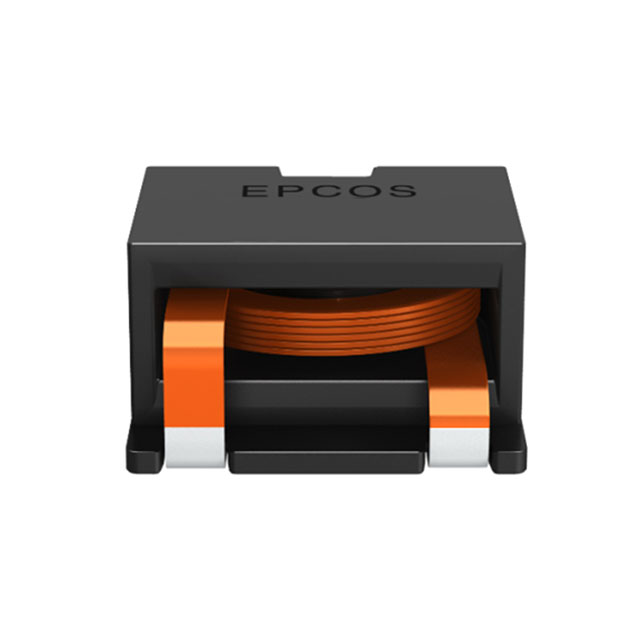
B82559A0153A016 (Alternative Substitute)
This EPCOS part represents a higher-performance alternative with significantly elevated current capacity (11 A) and substantially lower DC resistance (11.1 mOhm Max). The ±10% inductance tolerance is tighter than the main part. The part is AEC-Q200 qualified and rated for -40°C to 150°C operation. However, the footprint is substantially larger (18.70 x 17.30 x 9.60 mm) with a 3-lead configuration, making it unsuitable for direct PCB substitution without layout redesign. The part is classified as Obsolete, indicating no future availability and potential supply constraints.
Selection Guidance
For direct replacement in existing designs with minimal PCB modification, CLF10060NIT-150M-D is the appropriate choice. For new designs or applications requiring higher current capacity and lower losses, B82559A0153A016 may be considered if footprint constraints can be accommodated, though obsolescence status should be factored into long-term supply planning.
Frequently Asked Questions (FAQ)
Q: Can CLF10060NIT-150M-D be used as a direct drop-in replacement for CLF10040T-150M-H?
A: Electrical compatibility is confirmed. Both parts share identical 15 µH inductance, ferrite shielded drum core construction, and surface mount technology. However, the footprint dimensions differ: CLF10060NIT-150M-D measures 10.10 x 10.00 x 6.30 mm compared to 10.00 x 9.70 x 4.10 mm for the main part. PCB layout verification is required to confirm clearance and trace routing compatibility before implementation.
Q: What is the significance of the "Last Time Buy" status for CLF10060NIT-150M-D?
A: Last Time Buy indicates that TDK has announced end-of-life for this part number. Current inventory (1685 Pcs) represents the final production run. After available stock is exhausted, the part will no longer be manufactured or available through distribution channels. Long-term designs should plan for transition to actively produced alternatives.
Q: Why is B82559A0153A016 classified as Obsolete?
A: Obsolete status indicates the part has been discontinued and is no longer in active production. While limited inventory may exist through secondary distribution channels, no new manufacturing is occurring. This part should be considered only for legacy system support where supply can be secured through specialized distributors.
Q: Are all three parts RoHS3 compliant?
A: Yes. CLF10040T-150M-H, CLF10060NIT-150M-D, and B82559A0153A016 are all ROHS3 compliant with MSL rating of 1 (Unlimited), meeting current environmental and regulatory requirements for commercial and industrial applications.
Q: What is the impact of lower DC resistance in substitute parts?
A: Lower DC resistance reduces resistive power dissipation (I²R losses) during operation. CLF10060NIT-150M-D at 36 mOhm Max and B82559A0153A016 at 11.1 mOhm Max both provide improved efficiency compared to the main part at 40 mOhm. This results in lower operating temperature and extended component life in current-limited applications.
Q: Can B82559A0153A016 be used in applications designed for CLF10040T-150M-H?
A: Electrical substitution is feasible due to matching 15 µH inductance and ferrite core construction. However, the 3-lead configuration and significantly larger footprint (18.70 x 17.30 x 9.60 mm) preclude direct PCB mounting. Mechanical redesign and re-qualification would be required. The obsolete status further limits practical applicability for new implementations.
Q: What packaging differences exist between the substitute parts?
A: CLF10040T-150M-H is supplied in Tape & Reel (TR) format. CLF10060NIT-150M-D is supplied in Cut Tape (CT) format. B82559A0153A016 is available in both Cut Tape (CT) and Digi-Reel® formats. Packaging selection impacts handling, storage, and automated assembly compatibility.
Alternative Parts

SJ6012L2TP
Littelfuse Inc.
6 Alternative Parts

JMK107BBJ476MA-RE
Taiyo Yuden
10 Alternative Parts

GMK107BBJ475MA-T
Taiyo Yuden
5 Alternative Parts
SJ6020N2ARP
Littelfuse Inc.
3 Alternative Parts
SJ6025R2ATP
Littelfuse Inc.
4 Alternative Parts

2474-05L
API Delevan Inc.
1 Alternative Parts

4590R-684K
API Delevan Inc.
1 Alternative Parts

CM6560R-334
API Delevan Inc.
1 Alternative Parts

CM6460-104
API Delevan Inc.
1 Alternative Parts

5526-12
API Delevan Inc.
1 Alternative Parts