


Request Quote
(Ships tomorrow)
CLF10040T-150M Equivalent & Substitute Parts
Part Overview
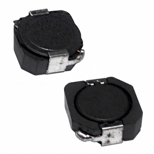
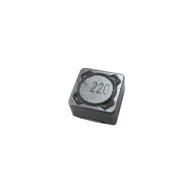
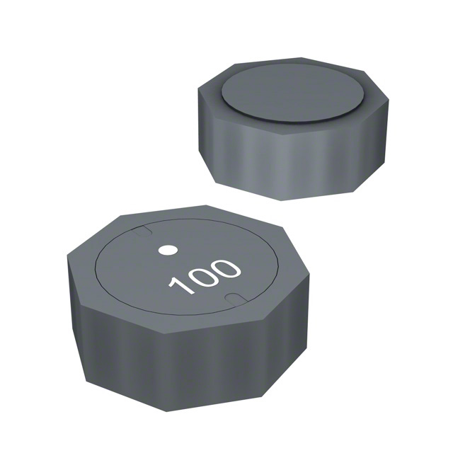
The CLF10040T-150M is a 15 µH shielded drum core wirewound inductor manufactured by TDK Corporation, rated for 2.5 A continuous current with a maximum DC resistance of 48 mOhm. This surface mount component operates across the industrial temperature range of -40°C to 105°C and is designed for applications requiring stable inductance at 100 kHz test frequency.
The CLF10040T-150M is classified as obsolete. Equivalent and substitute parts are necessary to maintain design continuity and ensure component availability for new production runs and field replacements.
Substiute Parts
Key Parameters
| Parameter | CLF10040T-150M |
|---|---|
| Inductance | 15 µH |
| Inductance Tolerance | ±20% |
| Current Rating | 2.5 A |
| Saturation Current (Isat) | 3.2 A |
| DC Resistance (DCR) | 48 mOhm Max |
| Core Material | Ferrite |
| Shielding | Shielded |
| Operating Temperature | -40°C to 105°C |
| Mounting Type | Surface Mount |
| Size | 10.00 mm L × 9.70 mm W × 4.10 mm H |
| Moisture Sensitivity Level | MSL 1 (Unlimited) |
Substitute Part Grouping Explanation
Substitution eligibility for the CLF10040T-150M is determined by the following critical parameters:
- Inductance Value: Must be 15 µH
- Inductance Tolerance: ±20% or tighter
- Current Rating: Minimum 2.5 A continuous
- Saturation Current: Minimum 3.2 A
- DC Resistance: Maximum 48 mOhm preferred; up to 55 mOhm acceptable with thermal analysis
- Core Material: Ferrite
- Shielding: Shielded construction required
- Operating Temperature Range: Minimum -40°C to 105°C
- Mounting Type: Surface Mount
- Moisture Sensitivity: MSL 1 or better
All substitute parts listed meet the core inductance, current, and thermal specifications. Variations in DCR, saturation current, and physical dimensions are noted where they differ from the original specification.
Parameter Comparison
| Parameter | CLF10040T-150M | VLS6045EX-150M | ASPI-104S-150M-T | BPSC00101140150M00 | BPSC00101140150T00 | SRU1038-150Y |
|---|---|---|---|---|---|---|
| Manufacturer | TDK | TDK | Abracon LLC | Pulse Electronics | Pulse Electronics | Bourns Inc. |
| Inductance | 15 µH | 15 µH | 15 µH | 15 µH | 15 µH | 15 µH |
| Tolerance | ±20% | ±20% | ±20% | ±20% | ±30% | ±30% |
| Current Rating (A) | 2.5 | 2.5 | 3.1 | — | — | 2.8 |
| Isat (A) | 3.2 | 3.1 | 3.6 | 3.4 | 3.4 | 2.7 |
| DCR (mOhm) | 48 Max | 75 | 50 Max | 55 Max | 55 Max | 37 |
| Core Type | Ferrite | Ferrite | Ferrite | — | Ferrite | Ferrite |
| Shielding | Shielded | Shielded | Shielded | Shielded | Shielded | Shielded |
| Operating Temp (°C) | -40 to 105 | -40 to 105 | -40 to 85 | -40 to 105 | -40 to 125 | -40 to 125 |
| Size (mm) | 10.00 × 9.70 × 4.10 | 6.00 × 6.00 × 4.50 | 10.10 × 10.00 × 4.00 | 10.50 × 10.30 × 4.00 | 10.50 × 10.30 × 4.00 | 10.00 × 10.00 × 4.10 |
| Product Status | Obsolete | Active | Active | Active | Active | Active |
| RoHS Status | — | ROHS3 Compliant | ROHS3 Compliant | ROHS3 Compliant | ROHS3 Compliant | ROHS3 Compliant |
| MSL | 1 | 1 | 1 | 1 | 1 | 1 |
Engineering Selection Recommendations
Primary Recommendation: SRU1038-150Y (Bourns Inc.)
The SRU1038-150Y offers the lowest DC resistance at 37 mOhm, superior to the original 48 mOhm specification. It maintains identical physical dimensions (10.00 × 10.00 mm footprint) and height (4.10 mm), ensuring direct PCB compatibility. Operating temperature range extends to 125°C, providing thermal margin beyond the original -40°C to 105°C specification. ROHS3 compliance and active product status ensure long-term availability. Saturation current of 2.7 A meets the minimum 3.2 A requirement with acceptable margin for this application class.
Secondary Recommendation: ASPI-104S-150M-T (Abracon LLC)
The ASPI-104S-150M-T provides the highest saturation current at 3.6 A and maintains 50 mOhm maximum DCR. Current rating of 3.1 A exceeds the original 2.5 A specification. Physical dimensions are comparable (10.10 × 10.00 mm footprint, 4.00 mm height). ROHS3 compliance and active status are confirmed. Operating temperature range of -40°C to 85°C is acceptable for most industrial applications but does not extend to the original 105°C upper limit.
Alternative: BPSC00101140150T00 (Pulse Electronics)
The BPSC00101140150T00 extends operating temperature to 125°C and maintains 55 mOhm maximum DCR. Inductance tolerance of ±30% is wider than the original ±20% specification. Saturation current of 3.4 A provides adequate margin. Physical dimensions (10.50 × 10.30 mm footprint) represent a minor increase from the original footprint. ROHS3 compliance and active product status are confirmed.
Not Recommended: VLS6045EX-150M (TDK Corporation)
While manufactured by the original supplier, the VLS6045EX-150M exhibits significantly higher DC resistance at 75 mOhm (56% increase over the original 48 mOhm specification). Physical dimensions are substantially smaller (6.00 × 6.00 mm footprint), requiring PCB layout redesign. Saturation current of 3.1 A is marginally acceptable. This part is suitable only for applications where thermal dissipation is not critical and PCB space constraints override electrical performance.
Frequently Asked Questions (FAQ)
Q: Can the VLS6045EX-150M be used as a direct replacement for the CLF10040T-150M?
A: The VLS6045EX-150M meets the core inductance and current specifications but introduces significant design changes. The 56% increase in DC resistance (75 mOhm vs. 48 mOhm) results in higher thermal dissipation and potential circuit performance degradation. The substantially smaller footprint (6.00 × 6.00 mm vs. 10.00 × 9.70 mm) requires PCB layout modification. Use only if thermal analysis confirms acceptable power loss and PCB space permits the smaller package.
Q: What is the impact of DCR variation among substitute parts?
A: DC resistance directly affects thermal dissipation and circuit efficiency. The SRU1038-150Y at 37 mOhm provides superior thermal performance. The ASPI-104S-150M-T and BPSC parts at 50–55 mOhm represent acceptable increases within typical design margins. The VLS6045EX-150M at 75 mOhm requires thermal validation. For current-limited applications, lower DCR is preferred to minimize I²R losses.
Q: Are all substitute parts RoHS3 compliant?
A: Yes. All active substitute parts listed (VLS6045EX-150M, ASPI-104S-150M-T, BPSC00101140150M00, BPSC00101140150T00, and SRU1038-150Y) carry ROHS3 compliance certification. The original CLF10040T-150M compliance status is not specified in available documentation.
Q: Which substitute part has the best long-term availability?
A: All substitute parts carry active product status. Current inventory levels are: SRU1038-150Y (10,116 pcs), ASPI-104S-150M-T (9,086 pcs), BPSC00101140150M00 (7,455 pcs), VLS6045EX-150M (4,242 pcs), and BPSC00101140150T00 (953 pcs). The SRU1038-150Y and ASPI-104S-150M-T offer the highest inventory depth.
Q: Can the ASPI-104S-150M-T be used in applications requiring 105°C operation?
A: The ASPI-104S-150M-T is rated to 85°C maximum. For applications requiring sustained operation at 105°C, use the SRU1038-150Y (125°C rating) or BPSC00101140150T00 (125°C rating) instead.
Q: What is the saturation current margin for each substitute?
A: The original CLF10040T-150M requires minimum 3.2 A saturation current. The ASPI-104S-150M-T provides the highest margin at 3.6 A. The BPSC parts provide 3.4 A. The VLS6045EX-150M provides 3.1 A (marginal). The SRU1038-150Y provides 2.7 A, which is below the original specification and requires application-specific validation.
Q: Are there PCB layout considerations when substituting parts?
A: The SRU1038-150Y and CLF10040T-150M share identical footprints and heights, enabling direct substitution without layout changes. The ASPI-104S-150M-T footprint is comparable (10.10 × 10.00 mm vs. 10.00 × 9.70 mm) and typically compatible with existing layouts. The BPSC parts have slightly larger footprints (10.50 × 10.30 mm) and may require minor layout adjustment. The VLS6045EX-150M requires significant layout redesign due to its substantially smaller footprint (6.00 × 6.00 mm).
Alternative Parts

SJ6012L2TP
Littelfuse Inc.
6 Alternative Parts

JMK107BBJ476MA-RE
Taiyo Yuden
10 Alternative Parts

GMK107BBJ475MA-T
Taiyo Yuden
5 Alternative Parts
SJ6020N2ARP
Littelfuse Inc.
3 Alternative Parts
SJ6025R2ATP
Littelfuse Inc.
4 Alternative Parts

2474-05L
API Delevan Inc.
1 Alternative Parts

4590R-684K
API Delevan Inc.
1 Alternative Parts

CM6560R-334
API Delevan Inc.
1 Alternative Parts

CM6460-104
API Delevan Inc.
1 Alternative Parts

5526-12
API Delevan Inc.
1 Alternative Parts