


Request Quote
(Ships tomorrow)
CDRH74-180MC Equivalent & Substitute Parts Reference
Part Overview
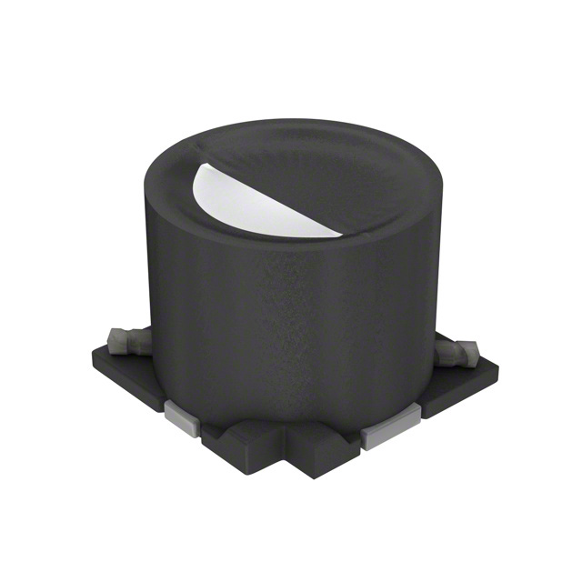
The CDRH74-180MC is an 18 µH shielded inductor manufactured by Sumida America Components Inc., rated for 1.31 A with a maximum DC resistance of 91 mOhm. This component is classified as obsolete, necessitating identification of active equivalent parts for new procurement and design continuity. The part features a nonstandard surface mount package with ferrite core construction and operates across the temperature range of -40°C to 100°C.
Due to its obsolete status, sourcing direct replacements from active product lines is essential for ongoing production and maintenance applications. Equivalent substitutes must maintain the core electrical parameters: 18 µH inductance at ±20% tolerance, 1.31 A minimum current rating, shielded construction, and compatible surface mount packaging.
Substiute Parts
Key Parameters
| Parameter | Value | Unit | Substitution Criticality |
|---|---|---|---|
| Inductance | 18 | µH | Critical |
| Inductance Tolerance | ±20% | % | Critical |
| Current Rating | 1.31 | A | Critical |
| DC Resistance (Max) | 91 | mOhm | Critical |
| Shielding | Shielded | — | Critical |
| Core Material | Ferrite | — | Important |
| Mounting Type | Surface Mount | — | Critical |
| Operating Temperature | -40°C to 100°C | °C | Important |
| Package Type | Nonstandard | — | Critical |
| Size (L × W) | 7.30 × 7.30 | mm | Critical |
| Height (Max) | 4.50 | mm | Critical |
| RoHS Compliance | RoHS3 Compliant | — | Important |
| Moisture Sensitivity Level | 1 (Unlimited) | — | Important |
Substitute Part Grouping Explanation
Substitution logic for the CDRH74-180MC is based on strict electrical and mechanical parameter matching within the allowed tolerance specifications. The following criteria determine valid equivalency:
Critical Matching Parameters:
- Inductance value of 18 µH at ±20% tolerance
- Current rating equal to or exceeding 1.31 A
- DC resistance not exceeding 91 mOhm maximum
- Shielded construction for electromagnetic interference control
- Surface mount nonstandard package with dimensions 7.30 × 7.30 mm footprint
- Height seated maximum of 4.50 mm
Secondary Compatibility Parameters:
- Operating temperature range encompassing -40°C to 100°C minimum
- Ferrite or equivalent core material
- Moisture sensitivity level 1 (unlimited)
- RoHS3 compliance for regulatory alignment
Substitutes are classified into two categories: direct equivalents (identical electrical and mechanical specifications with active product status) and similar alternatives (meeting all critical parameters with minor variations in secondary specifications).
Parameter Comparison
| Parameter | CDRH74-180MC (Main) | CDRH74NP-180MC-B (Direct) | P1167.183NLT (Similar) | SLF7045T-220MR90-PF (Similar) |
|---|---|---|---|---|
| Manufacturer | Sumida America Components Inc. | Sumida America Components Inc. | Pulse Electronics | TDK Corporation |
| Inductance (µH) | 18 | 18 | 18 | 22 |
| Tolerance | ±20% | ±20% | ±20% | ±20% |
| Current Rating (A) | 1.31 | 1.31 | 1.5 | 1.34 |
| DC Resistance Max (mOhm) | 91 | 91 | 73 | 73.2 |
| Shielding | Shielded | Shielded | Shielded | Shielded |
| Core Material | Ferrite | Ferrite | Not specified | Ferrite |
| Mounting Type | Surface Mount | Surface Mount | Surface Mount | Surface Mount |
| Operating Temperature (°C) | -40 to 100 | -40 to 100 | -40 to 130 | -40 to 105 |
| Size L × W (mm) | 7.30 × 7.30 | 7.30 × 7.30 | 7.54 × 7.54 | 7.00 × 7.00 |
| Height Max (mm) | 4.50 | 4.50 | 4.50 | 4.80 |
| Product Status | Obsolete | Active | Active | Not For New Designs |
| RoHS Status | Non-compliant | ROHS3 Compliant | ROHS3 Compliant | ROHS3 Compliant |
| Packaging | Nonstandard | Tape & Reel (TR) | Tape & Reel (TR) | Cut Tape (CT) & Digi-Reel® |
Engineering Selection Recommendations
CDRH74NP-180MC-B (Recommended Primary Substitute)
The CDRH74NP-180MC-B is the optimal direct replacement for the obsolete CDRH74-180MC. Both parts are manufactured by Sumida America Components Inc. and share identical electrical specifications: 18 µH inductance, 1.31 A current rating, and 91 mOhm maximum DC resistance. The substitute maintains the same ferrite core construction, shielded design, and nonstandard surface mount package with identical footprint (7.30 × 7.30 mm) and height (4.50 mm). The CDRH74NP-180MC-B carries active product status and ROHS3 compliance, eliminating regulatory and supply chain concerns associated with the obsolete main part. Packaging is available in Tape & Reel format, supporting automated assembly processes.
P1167.183NLT (Secondary Substitute)
The P1167.183NLT from Pulse Electronics meets all critical electrical parameters with enhanced performance characteristics. It maintains 18 µH inductance at ±20% tolerance and exceeds the current rating requirement at 1.5 A. The DC resistance of 73 mOhm is superior to the 91 mOhm maximum specification. The part features wirewound construction with shielding and operates across -40°C to 130°C, providing extended temperature coverage. Footprint dimensions of 7.54 × 7.54 mm represent a minor increase from the 7.30 × 7.30 mm standard, requiring PCB layout verification. Height remains compatible at 4.50 mm maximum. Product status is active with ROHS3 compliance. This substitute is suitable for applications where improved DC resistance performance and extended temperature range provide design benefits.
SLF7045T-220MR90-PF (Tertiary Substitute)
The SLF7045T-220MR90-PF from TDK Corporation presents a partial alternative with notable parameter deviations. The inductance value of 22 µH exceeds the 18 µH specification by 22%, which falls within the ±20% tolerance band of the original part but represents a significant shift in circuit behavior. Current rating of 1.34 A marginally exceeds the 1.31 A requirement, while DC resistance of 73.2 mOhm improves upon the 91 mOhm maximum. The part features drum core wirewound construction with ferrite material and shielding. Footprint dimensions of 7.00 × 7.00 mm are smaller than the standard, and height of 4.80 mm exceeds the 4.50 mm maximum by 0.30 mm, requiring mechanical clearance verification. Product status is "Not For New Designs," limiting suitability for new development. This substitute is applicable only to legacy maintenance scenarios where inductance tolerance and height clearance can be accommodated.
Frequently Asked Questions (FAQ)
Q1: Can the CDRH74NP-180MC-B be used as a direct drop-in replacement for the CDRH74-180MC?
A: Yes. The CDRH74NP-180MC-B is a direct electrical and mechanical equivalent. Both parts share identical inductance (18 µH), current rating (1.31 A), DC resistance (91 mOhm maximum), core material (ferrite), shielding, and package dimensions (7.30 × 7.30 × 4.50 mm). The primary difference is product status: the substitute is active with ROHS3 compliance, whereas the original is obsolete and non-compliant. No circuit redesign or PCB modification is required.
Q2: What are the key differences between the P1167.183NLT and the original CDRH74-180MC?
A: The P1167.183NLT maintains the same 18 µH inductance and ±20% tolerance but offers improved electrical performance: current rating of 1.5 A versus 1.31 A, and DC resistance of 73 mOhm versus 91 mOhm maximum. The substitute uses wirewound construction and extends operating temperature to 130°C. Mechanical differences include footprint dimensions of 7.54 × 7.54 mm (versus 7.30 × 7.30 mm) and identical height of 4.50 mm. PCB layout verification is required to accommodate the slightly larger footprint.
Q3: Why is the SLF7045T-220MR90-PF listed as a substitute if the inductance is 22 µH instead of 18 µH?
A: The SLF7045T-220MR90-PF meets substitution criteria because its 22 µH inductance falls within the ±20% tolerance specification of the original 18 µH part (tolerance range: 14.4 µH to 21.6 µH). However, this represents a significant inductance shift that may affect circuit performance. This substitute is recommended only for legacy maintenance applications where inductance tolerance has been validated. It is not suitable for new designs due to its "Not For New Designs" product status.
Q4: What is the impact of the height difference in the SLF7045T-220MR90-PF?
A: The SLF7045T-220MR90-PF has a maximum seated height of 4.80 mm, compared to 4.50 mm for the original part. This 0.30 mm increase may exceed available clearance in compact PCB assemblies, particularly in applications with height-constrained enclosures or stacked component arrangements. Mechanical clearance verification is mandatory before substitution.
Q5: Are all substitute parts RoHS3 compliant?
A: The CDRH74NP-180MC-B and P1167.183NLT are both ROHS3 compliant. The SLF7045T-220MR90-PF is also ROHS3 compliant. The original CDRH74-180MC is RoHS non-compliant. For applications requiring regulatory compliance with RoHS3 standards, all three substitutes are acceptable from a compliance perspective.
Q6: What packaging formats are available for these substitutes?
A: The CDRH74NP-180MC-B is supplied in Tape & Reel (TR) format, supporting automated pick-and-place assembly. The P1167.183NLT is also available in Tape & Reel format. The SLF7045T-220MR90-PF is supplied in Cut Tape (CT) and Digi-Reel® format. Packaging selection should align with assembly process requirements and inventory management practices.
Q7: Which substitute should be selected for new product designs?
A: The CDRH74NP-180MC-B is the recommended choice for new designs. It provides direct electrical and mechanical equivalency, active product status, ROHS3 compliance, and reliable long-term availability. The P1167.183NLT is suitable if improved DC resistance performance and extended temperature range provide design advantages, provided PCB layout accommodates the slightly larger footprint. The SLF7045T-220MR90-PF should not be used for new designs due to its "Not For New Designs" status.
Q8: How do the DC resistance values affect circuit performance?
A: DC resistance directly impacts power dissipation and voltage drop across the inductor. The original CDRH74-180MC specifies 91 mOhm maximum. The CDRH74NP-180MC-B maintains this specification. The P1167.183NLT and SLF7045T-220MR90-PF both offer 73 mOhm maximum, reducing resistive losses by approximately 20%. Lower DC resistance is beneficial in high-current applications and reduces thermal stress on the component.
Q9: What is the significance of the inductance test frequency?
A: The CDRH74-180MC and CDRH74NP-180MC-B specify inductance measurement at 1 kHz. The P1167.183NLT and SLF7045T-220MR90-PF specify measurement at 100 kHz. Inductance values can vary with frequency due to core material properties. For applications operating at frequencies significantly different from the test frequency, frequency-dependent inductance characteristics should be evaluated using manufacturer datasheets.
Q10: Are there any moisture sensitivity concerns with these parts?
A: All parts listed, including the original CDRH74-180MC and all substitutes, carry Moisture Sensitivity Level (MSL) 1, classified as "Unlimited." This designation indicates no moisture sensitivity restrictions during storage, handling, or assembly. Standard component storage practices are sufficient; no special desiccant packaging or baking procedures are required.
Alternative Parts

SJ6012L2TP
Littelfuse Inc.
6 Alternative Parts

JMK107BBJ476MA-RE
Taiyo Yuden
10 Alternative Parts

GMK107BBJ475MA-T
Taiyo Yuden
5 Alternative Parts
SJ6020N2ARP
Littelfuse Inc.
3 Alternative Parts
SJ6025R2ATP
Littelfuse Inc.
4 Alternative Parts

2474-05L
API Delevan Inc.
1 Alternative Parts

4590R-684K
API Delevan Inc.
1 Alternative Parts

CM6560R-334
API Delevan Inc.
1 Alternative Parts

CM6460-104
API Delevan Inc.
1 Alternative Parts

5526-12
API Delevan Inc.
1 Alternative Parts