


Request Quote
(Ships tomorrow)
CDRH74-121MC Equivalent & Substitute Parts
Part Overview
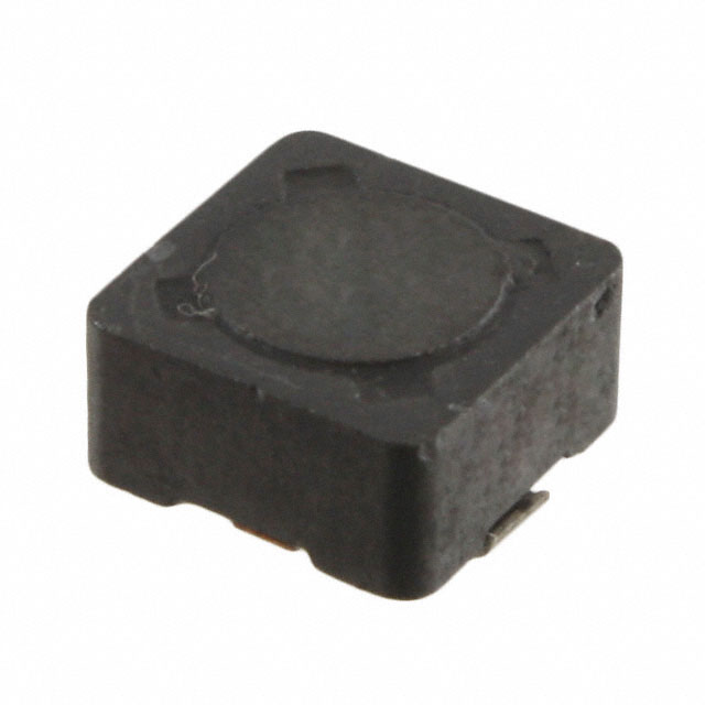
The CDRH74-121MC is a 120 µH shielded surface mount inductor manufactured by Sumida America Components Inc., rated for 520 mA continuous current with a maximum DC resistance of 660 mOhm. This component operates across the temperature range of -40°C to 100°C and features a ferrite core construction in a nonstandard 7.30mm × 7.30mm package footprint.
The CDRH74-121MC has reached obsolete product status. Identifying equivalent and substitute inductors is necessary to maintain design continuity, ensure supply chain availability, and support ongoing production requirements for applications utilizing this component specification.
Substiute Parts
Key Parameters
| Parameter | Value | Unit |
|---|---|---|
| Inductance | 120 | µH |
| Inductance Tolerance | ±20 | % |
| Current Rating | 520 | mA |
| DC Resistance (DCR) Maximum | 660 | mOhm |
| Shielding | Shielded | — |
| Core Material | Ferrite | — |
| Mounting Type | Surface Mount | — |
| Operating Temperature Range | -40 to 100 | °C |
| Package Dimensions (L × W) | 7.30 × 7.30 | mm |
| Height (Seated Maximum) | 4.50 | mm |
Substitute Part Grouping Explanation
Substitute inductors for the CDRH74-121MC are classified based on strict electrical and mechanical parameter alignment:
Direct Electrical Equivalents maintain identical inductance values (120 µH), current ratings (520 mA or higher), and DC resistance specifications (660 mOhm or lower). These parts preserve the original circuit performance without design modification.
Similar Functional Alternatives provide comparable inductance within the ±20% tolerance band, support equivalent or higher current ratings, and maintain shielded ferrite core construction. These parts accommodate minor circuit parameter variations while preserving core functionality.
Critical Substitution Parameters:
- Inductance value and tolerance
- Current rating (continuous)
- DC resistance (maximum)
- Shielding type
- Core material
- Surface mount package compatibility
- Operating temperature range
Parameter Comparison
| Parameter | CDRH74-121MC | CDRH74NP-121MC-B | DR74-151-R | P1167.124NLT |
|---|---|---|---|---|
| Manufacturer | Sumida America Components Inc. | Sumida America Components Inc. | Eaton - Electronics Division | Pulse Electronics |
| Inductance (µH) | 120 | 120 | 150 | 120 |
| Inductance Tolerance | ±20% | ±20% | ±20% | ±20% |
| Current Rating (mA) | 520 | 520 | 690 | 570 |
| DC Resistance Maximum (mOhm) | 660 | 660 | 591 | 530 |
| Shielding | Shielded | Shielded | Shielded | Shielded |
| Core Material | Ferrite | Ferrite | Ferrite | Not specified |
| Core Type | Standard | Standard | Drum Core, Wirewound | Wirewound |
| Mounting Type | Surface Mount | Surface Mount | Surface Mount | Surface Mount |
| Operating Temperature Range (°C) | -40 to 100 | -40 to 100 | -40 to 125 | -40 to 130 |
| Package Dimensions L × W (mm) | 7.30 × 7.30 | 7.30 × 7.30 | 7.60 × 7.60 | 7.54 × 7.54 |
| Height Seated Maximum (mm) | 4.50 | 4.50 | 4.35 | 4.50 |
| Product Status | Obsolete | Active | Active | Active |
| RoHS Compliance | Non-compliant | ROHS3 Compliant | ROHS3 Compliant | ROHS3 Compliant |
| Packaging | Nonstandard | Tape & Reel (TR) | Tape & Reel (TR) | Nonstandard |
Engineering Selection Recommendations
CDRH74NP-121MC-B is the primary direct equivalent for CDRH74-121MC replacement. This part maintains identical electrical specifications (120 µH inductance, 520 mA current rating, 660 mOhm maximum DCR) and mechanical dimensions (7.30mm × 7.30mm footprint, 4.50mm height). The CDRH74NP-121MC-B is manufactured by the same supplier (Sumida America Components Inc.) and carries Active product status with ROHS3 compliance certification. Packaging is provided in Tape & Reel format, supporting automated assembly processes.
DR74-151-R functions as a similar alternative when circuit design permits inductance variation within tolerance specifications. This Eaton inductor provides 150 µH inductance (25% above the original specification, within ±20% tolerance band), supports higher current capacity (690 mA versus 520 mA), and delivers superior DC resistance performance (591 mOhm versus 660 mOhm maximum). The DR74-151-R extends operating temperature range to -40°C to 125°C and features drum core wirewound construction. Package footprint dimensions (7.60mm × 7.60mm) represent a minor increase from the original 7.30mm specification. ROHS3 compliance and Active product status are confirmed.
P1167.124NLT provides an alternative for applications where lower DC resistance is advantageous. This Pulse Electronics inductor maintains 120 µH inductance specification, supports 570 mA current rating (50 mA above original), and achieves 530 mOhm maximum DC resistance (130 mOhm improvement). Operating temperature extends to -40°C to 130°C. Package dimensions (7.54mm × 7.54mm) and height (4.50mm) remain compatible with original footprint requirements. ROHS3 compliance is confirmed.
Selection between these substitutes depends on circuit tolerance for inductance variation, thermal operating requirements, and DC resistance performance priorities.
Frequently Asked Questions (FAQ)
Q: Can CDRH74NP-121MC-B directly replace CDRH74-121MC without circuit modification?
A: Yes. The CDRH74NP-121MC-B maintains identical electrical parameters (120 µH ±20%, 520 mA, 660 mOhm maximum DCR) and mechanical dimensions (7.30mm × 7.30mm, 4.50mm height). Both components feature shielded ferrite core construction and surface mount packaging. Direct substitution is supported without design changes.
Q: What are the implications of using DR74-151-R as a substitute?
A: The DR74-151-R provides 150 µH inductance instead of 120 µH, representing a 25% increase. This variation falls within the ±20% tolerance specification but will alter circuit inductance characteristics. The substitute offers improved current capacity (690 mA versus 520 mA) and lower DC resistance (591 mOhm versus 660 mOhm). Package footprint increases slightly (7.60mm × 7.60mm versus 7.30mm × 7.30mm). Circuit analysis is required to confirm compatibility with application requirements.
Q: How do package dimension differences affect PCB layout?
A: The CDRH74-121MC and CDRH74NP-121MC-B share identical footprints (7.30mm × 7.30mm, 4.50mm height) and require no layout modification. The DR74-151-R footprint (7.60mm × 7.60mm, 4.35mm height) represents a 0.30mm increase in length and width but maintains compatible height. The P1167.124NLT footprint (7.54mm × 7.54mm, 4.50mm height) requires minimal layout adjustment. PCB pad spacing verification is recommended for all substitutes.
Q: What is the significance of RoHS compliance differences?
A: The original CDRH74-121MC is RoHS non-compliant. All substitute parts (CDRH74NP-121MC-B, DR74-151-R, P1167.124NLT) carry ROHS3 compliance certification. For applications subject to RoHS regulatory requirements, substitution to any of these parts ensures compliance. For legacy systems without RoHS mandates, compliance status does not affect functional performance.
Q: How do operating temperature ranges compare?
A: The CDRH74-121MC operates across -40°C to 100°C. The CDRH74NP-121MC-B maintains this identical range. The DR74-151-R extends to -40°C to 125°C, and the P1167.124NLT extends to -40°C to 130°C. For applications requiring operation above 100°C, DR74-151-R or P1167.124NLT provide extended thermal capability.
Q: What packaging format differences exist?
A: The CDRH74-121MC uses nonstandard packaging. The CDRH74NP-121MC-B is supplied in Tape & Reel (TR) format, supporting automated pick-and-place assembly. The DR74-151-R is also supplied in Tape & Reel format. The P1167.124NLT uses nonstandard packaging similar to the original. For high-volume production requiring automated assembly, CDRH74NP-121MC-B or DR74-151-R are preferred.
Q: Are there DC resistance performance differences between substitutes?
A: The CDRH74-121MC specifies 660 mOhm maximum DCR. The CDRH74NP-121MC-B maintains this specification. The DR74-151-R achieves 591 mOhm (69 mOhm improvement), and the P1167.124NLT achieves 530 mOhm (130 mOhm improvement). Lower DC resistance reduces power dissipation and heat generation. Applications sensitive to resistive losses benefit from DR74-151-R or P1167.124NLT selection.
Alternative Parts

SJ6012L2TP
Littelfuse Inc.
6 Alternative Parts

JMK107BBJ476MA-RE
Taiyo Yuden
10 Alternative Parts

GMK107BBJ475MA-T
Taiyo Yuden
5 Alternative Parts
SJ6020N2ARP
Littelfuse Inc.
3 Alternative Parts
SJ6025R2ATP
Littelfuse Inc.
4 Alternative Parts

2474-05L
API Delevan Inc.
1 Alternative Parts

4590R-684K
API Delevan Inc.
1 Alternative Parts

CM6560R-334
API Delevan Inc.
1 Alternative Parts

CM6460-104
API Delevan Inc.
1 Alternative Parts

5526-12
API Delevan Inc.
1 Alternative Parts