


Request Quote
(Ships tomorrow)
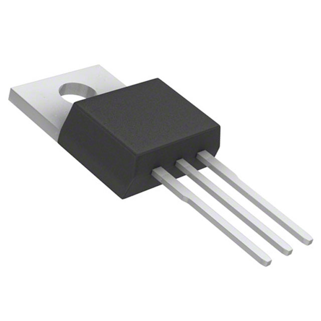
CDM22010-650 SL N-Channel MOSFET 650V 10A TO-220 Equivalent & Substitute Parts
Part Overview
The CDM22010-650 SL is an N-Channel MOSFET manufactured by Central Semiconductor Corp, rated for 650V drain-to-source voltage and 10A continuous drain current in TO-220-3 package configuration. This component is classified as obsolete product status. Due to obsolescence and limited availability from the original manufacturer, equivalent substitute parts from active product lines are necessary for ongoing design support and procurement continuity. Substitute components must maintain electrical compatibility within the specified parameter ranges while accommodating minor variations in performance characteristics.
Substiute Parts
Key Parameters
| Parameter | CDM22010-650 SL | Unit |
|---|---|---|
| FET Type | N-Channel | — |
| Technology | MOSFET (Metal Oxide) | — |
| Drain to Source Voltage (Vdss) | 650 | V |
| Current - Continuous Drain (Id) @ 25°C | 10 | A (Ta) |
| Drive Voltage (Max Rds On) | 10 | V |
| Rds On (Max) @ Id, Vgs | 1 | Ohm @ 5A, 10V |
| Vgs(th) (Max) @ Id | 4 | V @ 250µA |
| Gate Charge (Qg) (Max) @ Vgs | 20 | nC @ 10V |
| Vgs (Max) | 30 | V |
| Input Capacitance (Ciss) (Max) @ Vds | 1168 | pF @ 25V |
| Power Dissipation (Max) | 2 (Ta), 156 (Tc) | W |
| Operating Temperature | -55 to 150 | °C (TJ) |
| Mounting Type | Through Hole | — |
| Package / Case | TO-220-3 | — |
| RoHS Status | ROHS3 Compliant | — |
| Moisture Sensitivity Level (MSL) | 1 (Unlimited) | — |
Substitute Part Grouping Explanation
Substitute parts for the CDM22010-650 SL are selected based on the following electrical and mechanical compatibility criteria:
Primary Substitution Parameters:
- FET Type: N-Channel (mandatory match)
- Technology: MOSFET Metal Oxide (mandatory match)
- Package / Case: TO-220-3 (mandatory match)
- Mounting Type: Through Hole (mandatory match)
- Operating Temperature Range: -55°C to 150°C (mandatory match)
- Drain to Source Voltage (Vdss): Equal to or greater than 650V
- Continuous Drain Current (Id): Equal to or greater than 10A
- Drive Voltage: 10V (standard gate drive voltage)
- RoHS3 Compliance: Required for regulatory alignment
Substitution Logic: The CDM22010-650 SL operates at 650V with 10A continuous current capability. Substitute parts meeting or exceeding these voltage and current ratings are electrically compatible. Parts rated at 800V Vdss provide higher voltage margin while maintaining the same gate drive voltage and temperature operating range. Current ratings of 4.5A to 6.2A represent functional alternatives where thermal management and circuit design accommodate the reduced current capacity. All substitute parts maintain TO-220-3 package compatibility and through-hole mounting configuration.
Parameter Comparison
| Parameter | CDM22010-650 SL | IPP80R1K2P7XKSA1 | IPP80R900P7XKSA1 | IRFBC40APBF | IRFBC40PBF | STP7LN80K5 | Unit |
|---|---|---|---|---|---|---|---|
| Manufacturer | Central Semiconductor | Infineon Technologies | Infineon Technologies | Vishay Siliconix | Vishay Siliconix | STMicroelectronics | — |
| FET Type | N-Channel | N-Channel | N-Channel | N-Channel | N-Channel | N-Channel | — |
| Vdss | 650 | 800 | 800 | 600 | 600 | 800 | V |
| Id @ 25°C | 10 (Ta) | 4.5 (Tc) | 6 (Tc) | 6.2 (Tc) | 6.2 (Tc) | 5 (Tc) | A |
| Drive Voltage | 10 | 10 | 10 | 10 | 10 | 10 | V |
| Rds On (Max) @ Id, Vgs | 1 @ 5A, 10V | 1.2 @ 1.7A, 10V | 0.9 @ 2.2A, 10V | 1.2 @ 3.7A, 10V | 1.2 @ 3.7A, 10V | 1.15 @ 2.5A, 10V | Ohm |
| Vgs(th) (Max) @ Id | 4 @ 250µA | 3.5 @ 80µA | 3.5 @ 110µA | 4 @ 250µA | 4 @ 250µA | 5 @ 100µA | V |
| Gate Charge (Qg) (Max) @ Vgs | 20 @ 10V | 11 @ 10V | 15 @ 10V | 42 @ 10V | 60 @ 10V | 12 @ 10V | nC |
| Vgs (Max) | 30 | ±20 | ±20 | ±30 | ±20 | ±30 | V |
| Ciss (Max) @ Vds | 1168 @ 25V | 300 @ 500V | 350 @ 500V | 1036 @ 25V | 1300 @ 25V | 270 @ 100V | pF |
| Power Dissipation (Max) | 2 (Ta), 156 (Tc) | 37 (Tc) | 45 (Tc) | 125 (Tc) | 125 (Tc) | 85 (Tc) | W |
| Operating Temperature | -55 to 150 | -55 to 150 | -55 to 150 | -55 to 150 | -55 to 150 | -55 to 150 | °C (TJ) |
| Package / Case | TO-220-3 | TO-220-3 | TO-220-3 | TO-220-3 | TO-220-3 | TO-220-3 | — |
| Product Status | Obsolete | Active | Active | Active | Active | Active | — |
| RoHS Status | ROHS3 Compliant | ROHS3 Compliant | ROHS3 Compliant | ROHS3 Compliant | ROHS3 Compliant | ROHS3 Compliant | — |
| MSL | 1 (Unlimited) | 1 (Unlimited) | 1 (Unlimited) | 1 (Unlimited) | 1 (Unlimited) | 1 (Unlimited) | — |
Engineering Selection Recommendations
Product Status Consideration: The CDM22010-650 SL is classified as obsolete. All listed substitute parts maintain active product status from their respective manufacturers, ensuring long-term availability and continued technical support. Selection of active-status components eliminates supply chain risk associated with end-of-life products.
Regulatory Compliance: All substitute parts are ROHS3 compliant and carry MSL rating of 1 (Unlimited), matching the original component's compliance profile. REACH status varies: Infineon IPP80R series and STMicroelectronics STP7LN80K5 are REACH Unaffected; Vishay IRFBC40 series are REACH Affected. Component selection should align with end-application regulatory requirements.
Voltage Rating Alignment:
- Higher Voltage Substitutes (800V): IPP80R1K2P7XKSA1, IPP80R900P7XKSA1, and STP7LN80K5 provide 800V Vdss rating, exceeding the original 650V specification. These components offer enhanced voltage margin for applications requiring higher transient voltage protection.
- Lower Voltage Substitutes (600V): IRFBC40APBF and IRFBC40PBF are rated at 600V Vdss, below the original specification. These components are suitable only for applications where circuit design confirms maximum voltage stress remains below 600V.
Current Rating Considerations: Substitute parts are rated between 4.5A and 6.2A continuous drain current, below the original 10A specification. Circuit thermal design and current distribution must accommodate reduced current capacity. Higher power dissipation ratings in Vishay IRFBC40 series (125W Tc) and STMicroelectronics STP7LN80K5 (85W Tc) provide thermal performance suitable for sustained current operation.
Gate Drive Compatibility: All substitute parts operate at 10V drive voltage, matching the original component specification. Vgs(th) threshold voltages range from 3.5V to 5V, all within acceptable gate drive margins for standard PWM controller circuits.
Frequently Asked Questions (FAQ)
Q: Can the CDM22010-650 SL be directly replaced with any of these substitute parts?
A: Direct replacement depends on circuit voltage and current requirements. All substitute parts maintain TO-220-3 package compatibility and 10V gate drive voltage. However, current ratings (4.5A to 6.2A) are lower than the original 10A specification. Thermal analysis and current distribution verification are required before substitution. Voltage ratings vary: 800V substitutes provide margin above 650V; 600V substitutes operate below original specification.
Q: What is the difference between the Infineon IPP80R1K2P7XKSA1 and IPP80R900P7XKSA1?
A: Both are Infineon CoolMOS™ P7 series devices rated at 800V Vdss. The IPP80R900P7XKSA1 provides 6A continuous current with 0.9Ohm Rds On, compared to 4.5A and 1.2Ohm for the IPP80R1K2P7XKSA1. The IPP80R900P7XKSA1 offers superior current capacity and lower on-resistance, resulting in 45W power dissipation versus 37W. Gate charge is 15nC versus 11nC. Selection depends on circuit current requirements and thermal budget.
Q: Why do the Vishay IRFBC40 parts show different gate charge values?
A: IRFBC40PBF specifies 60nC gate charge at 10V, while IRFBC40APBF specifies 42nC at the same voltage. Both parts are electrically equivalent with identical voltage, current, and Rds On ratings. The gate charge difference reflects measurement or specification variation between part revisions. Both are suitable for substitution; gate drive circuit design should accommodate the higher 60nC value for IRFBC40PBF.
Q: Are the STMicroelectronics STP7LN80K5 and Infineon IPP80R900P7XKSA1 interchangeable?
A: Both parts are rated at 800V Vdss with similar current capacity (5A versus 6A) and comparable Rds On values (1.15Ohm versus 0.9Ohm). Gate charge specifications differ (12nC versus 15nC). Input capacitance is lower in STP7LN80K5 (270pF @ 100V versus 350pF @ 500V). Both are suitable substitutes; selection depends on gate drive circuit optimization and thermal performance requirements.
Q: What is the significance of the different Vgs(th) threshold voltages?
A: Threshold voltages range from 3.5V (Infineon) to 5V (STMicroelectronics). All values remain within acceptable gate drive margins for standard 10V to 15V PWM controller outputs. Lower threshold voltages (3.5V) enable faster switching response; higher values (5V) provide greater noise immunity. Gate drive circuit design should verify compatibility with controller output voltage and switching frequency requirements.
Q: Can I use a 600V rated substitute in a 650V application?
A: No. The IRFBC40APBF and IRFBC40PBF are rated at 600V Vdss, below the original 650V specification. These components are suitable only for applications where circuit analysis confirms maximum drain-to-source voltage remains below 600V under all operating conditions, including transient overvoltage events. Use of 800V rated substitutes is recommended for applications requiring 650V or higher voltage margin.
Q: What thermal considerations apply when substituting lower current-rated parts?
A: Substitute parts rated at 4.5A to 6.2A require thermal management for applications originally designed for 10A operation. Power dissipation at rated current increases due to higher Rds On values in some substitutes. Thermal design must verify that junction temperature remains within -55°C to 150°C operating range under worst-case ambient and load conditions. Heatsink sizing and thermal interface material selection may require adjustment.
Q: Are all substitute parts available in the same packaging variants?
A: All substitute parts are supplied in TO-220-3 package configuration with through-hole mounting. Supplier device packages vary: Infineon uses PG-TO220-3; Vishay uses TO-220AB; STMicroelectronics uses TO-220. These designations refer to manufacturer-specific package variants; all are mechanically and electrically compatible with standard TO-220-3 footprints.
Alternative Parts

SJ6012L2TP
Littelfuse Inc.
6 Alternative Parts

JMK107BBJ476MA-RE
Taiyo Yuden
10 Alternative Parts

GMK107BBJ475MA-T
Taiyo Yuden
5 Alternative Parts
SJ6020N2ARP
Littelfuse Inc.
3 Alternative Parts
SJ6025R2ATP
Littelfuse Inc.
4 Alternative Parts

2474-05L
API Delevan Inc.
1 Alternative Parts

4590R-684K
API Delevan Inc.
1 Alternative Parts

CM6560R-334
API Delevan Inc.
1 Alternative Parts

CM6460-104
API Delevan Inc.
1 Alternative Parts

5526-12
API Delevan Inc.
1 Alternative Parts