


Request Quote
(Ships tomorrow)
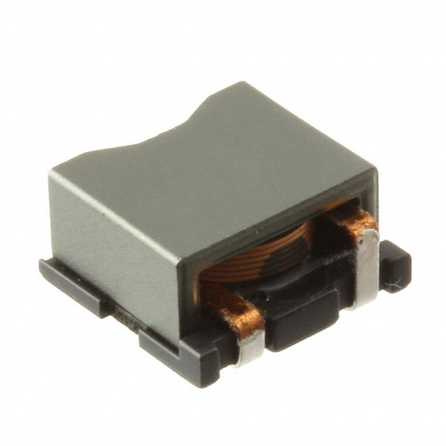
CDEP105MENP-3R3PC Equivalent & Substitute Parts
Part Overview
The CDEP105MENP-3R3PC is a 3.3 µH shielded inductor manufactured by Sumida America Components Inc., designed for surface mount applications requiring 6.5 A current rating and 15.1 mOhm maximum DC resistance. This component is classified as obsolete, necessitating identification of active equivalent parts for ongoing production and procurement requirements. The metal composite core construction provides shielding suitable for noise-sensitive circuit applications.
Substiute Parts
Key Parameters
| Parameter | Value |
|---|---|
| Inductance | 3.3 µH |
| Current Rating | 6.5 A |
| DC Resistance (DCR) | 15.1 mOhm Max |
| Saturation Current (Isat) | 12.8 A |
| Shielding | Shielded |
| Core Material | Metal Composite |
| Operating Temperature Range | -40°C to 125°C |
| Mounting Type | Surface Mount |
| Package Dimensions | 11.00 mm L × 10.00 mm W × 5.50 mm H |
| Inductance Tolerance | ±25% |
| RoHS Status | ROHS3 Compliant |
| Moisture Sensitivity Level | MSL 1 (Unlimited) |
Substitute Part Grouping Explanation
Substitution of the CDEP105MENP-3R3PC is determined by the following critical parameters:
Primary Matching Criteria:
- Inductance value: 3.3 µH (exact match required)
- Shielding: Shielded configuration mandatory
- Mounting type: Surface mount only
- Operating temperature range: -40°C to 125°C minimum
- RoHS3 compliance required
Secondary Compatibility Parameters:
- Current rating: Substitute must equal or exceed 6.5 A
- DC resistance: Lower or equal to 15.1 mOhm preferred for thermal performance
- Saturation current: Equal to or greater than 12.8 A
- Package dimensions: Nonstandard form factor; physical fit verification required
- Inductance tolerance: ±20% or tighter acceptable
The VLM10555T-3R3M7R2-2 from TDK Corporation meets all primary matching criteria and demonstrates superior electrical performance in secondary parameters, qualifying it as a direct substitute for the obsolete CDEP105MENP-3R3PC.
Parameter Comparison
| Parameter | CDEP105MENP-3R3PC (Sumida) | VLM10555T-3R3M7R2-2 (TDK) |
|---|---|---|
| Inductance | 3.3 µH | 3.3 µH |
| Inductance Tolerance | ±25% | ±20% |
| Current Rating | 6.5 A | 7.2 A |
| Saturation Current (Isat) | 12.8 A | 12 A |
| DC Resistance (DCR) | 15.1 mOhm Max | 9.55 mOhm Max |
| Shielding | Shielded | Shielded |
| Core Material | Metal Composite | Ferrite |
| Operating Temperature | -40°C to 125°C | -40°C to 125°C |
| Mounting Type | Surface Mount | Surface Mount |
| Package Dimensions (L × W × H) | 11.00 × 10.00 × 5.50 mm | 10.60 × 10.50 × 5.60 mm |
| RoHS Status | ROHS3 Compliant | ROHS3 Compliant |
| Moisture Sensitivity Level | MSL 1 | MSL 1 |
| Product Status | Obsolete | Active |
Engineering Selection Recommendations
The VLM10555T-3R3M7R2-2 is qualified as the substitute for CDEP105MENP-3R3PC based on the following engineering factors:
Compliance & Regulatory: Both parts maintain ROHS3 compliance and MSL 1 rating, ensuring compatibility with current manufacturing and environmental standards. The substitute part carries active product status, guaranteeing long-term availability and supply chain continuity.
Electrical Performance: The substitute demonstrates superior electrical characteristics: 7.2 A current rating exceeds the original 6.5 A requirement, and DC resistance of 9.55 mOhm is significantly lower than the original 15.1 mOhm maximum, resulting in reduced thermal dissipation and improved efficiency.
Physical Compatibility: Package dimensions are comparable within nonstandard form factor specifications. The substitute measures 10.60 × 10.50 × 5.60 mm versus the original 11.00 × 10.00 × 5.50 mm. PCB layout verification is required to confirm mechanical fit within existing footprints.
Operational Range: Identical operating temperature range (-40°C to 125°C) and inductance frequency test point (100 kHz) ensure functional equivalence in circuit applications.
Frequently Asked Questions (FAQ)
Q: Can the VLM10555T-3R3M7R2-2 directly replace the CDEP105MENP-3R3PC without circuit modification?
A: The substitute meets all electrical specifications and exceeds current and saturation ratings. However, physical PCB footprint verification is mandatory due to nonstandard package dimensions. The substitute dimensions (10.60 × 10.50 × 5.60 mm) differ slightly from the original (11.00 × 10.00 × 5.50 mm).
Q: What is the significance of the lower DC resistance in the substitute part?
A: The VLM10555T-3R3M7R2-2 exhibits 9.55 mOhm maximum DC resistance compared to 15.1 mOhm in the original. Lower DC resistance reduces I²R losses, decreasing thermal generation and improving overall circuit efficiency.
Q: Are there differences in core material between these parts?
A: Yes. The CDEP105MENP-3R3PC uses metal composite core material, while the VLM10555T-3R3M7R2-2 uses ferrite core material. Both are shielded configurations suitable for noise-sensitive applications. Core material differences may affect frequency response characteristics not specified in the provided parameters.
Q: What is the inductance tolerance difference, and does it matter?
A: The original part specifies ±25% tolerance, while the substitute offers ±20% tolerance. Tighter tolerance in the substitute provides improved inductance value consistency, beneficial for precision circuit applications.
Q: Is the substitute available in the same packaging format?
A: The original part is supplied in nonstandard packaging. The substitute (VLM10555T-3R3M7R2-2) is available in Tape & Reel (TR) format, which is standard for automated assembly processes and may differ from the original packaging configuration.
Q: How do the saturation current ratings compare?
A: The original CDEP105MENP-3R3PC has 12.8 A saturation current, while the substitute VLM10555T-3R3M7R2-2 has 12 A saturation current. Both exceed the 6.5 A operating current rating, providing adequate saturation margin for the application.
Alternative Parts

SJ6012L2TP
Littelfuse Inc.
6 Alternative Parts

JMK107BBJ476MA-RE
Taiyo Yuden
10 Alternative Parts

GMK107BBJ475MA-T
Taiyo Yuden
5 Alternative Parts
SJ6020N2ARP
Littelfuse Inc.
3 Alternative Parts
SJ6025R2ATP
Littelfuse Inc.
4 Alternative Parts

2474-05L
API Delevan Inc.
1 Alternative Parts

4590R-684K
API Delevan Inc.
1 Alternative Parts

CM6560R-334
API Delevan Inc.
1 Alternative Parts

CM6460-104
API Delevan Inc.
1 Alternative Parts

5526-12
API Delevan Inc.
1 Alternative Parts