


Request Quote
(Ships tomorrow)
CDCVF2510APWR Equivalent & Substitute Parts
Part Overview
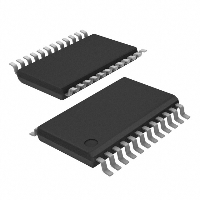
The CDCVF2510APWR is a PLL Clock Driver IC manufactured by Texas Instruments, designed for clock distribution and timing applications. This Surface Mount device operates at a maximum frequency of 175MHz with a 2:11 input-to-output ratio and supports LVTTL signal levels. The part is currently Active in production status with 15,762 units in stock.
Substitute parts are necessary when the primary part becomes unavailable, when alternative packaging formats are required, or when design specifications allow for compatible frequency or ratio variations within the same product family.
Substiute Parts
Key Parameters
| Parameter | Value |
|---|---|
| Manufacturer | Texas Instruments |
| Category | Clock/Timing |
| Type | PLL Clock Driver |
| Package / Case | 24-TSSOP (0.173", 4.40mm Width) |
| Frequency - Max | 175MHz |
| Ratio - Input:Output | 2:11 |
| Input Signal Type | LVTTL |
| Output Signal Type | LVTTL |
| Voltage - Supply | 3V ~ 3.6V |
| Operating Temperature | 0°C ~ 85°C |
| Mounting Type | Surface Mount |
| RoHS Status | ROHS3 Compliant |
| Moisture Sensitivity Level (MSL) | 1 (Unlimited) |
Substitute Part Grouping Explanation
Substitution eligibility for the CDCVF2510APWR is determined by the following critical parameters:
Mandatory Compatibility Parameters:
- Package / Case: 24-TSSOP (0.173", 4.40mm Width)
- Input Signal Type: LVTTL
- Output Signal Type: LVTTL
- Voltage - Supply: 3V ~ 3.6V
- Operating Temperature: 0°C ~ 85°C
- Mounting Type: Surface Mount
Variable Parameters Allowing Substitution:
- Frequency - Max: 175MHz or lower
- Ratio - Input:Output: Different ratios acceptable if application permits
- Product Status: Active or Obsolete (with design consideration)
- Packaging Format: Tape & Reel (TR) or alternative formats
The substitute parts listed below maintain all mandatory compatibility parameters while offering variations in frequency capability and input-to-output ratio configurations.
Parameter Comparison
| Part Number | Manufacturer | Frequency - Max | Ratio - Input:Output | Voltage - Supply | Operating Temperature | Package / Case | Product Status | Inventory (Pcs) |
|---|---|---|---|---|---|---|---|---|
| CDCVF2510APWR | Texas Instruments | 175MHz | 2:11 | 3V ~ 3.6V | 0°C ~ 85°C | 24-TSSOP | Active | 15,762 |
| CDCVF2510PWR | Texas Instruments | 175MHz | 2:11 | 3V ~ 3.6V | 0°C ~ 85°C | 24-TSSOP | Active | 17,883 |
| CDCVF2509PWR | Texas Instruments | 175MHz | 2:10 | 3V ~ 3.6V | 0°C ~ 85°C | 24-TSSOP | Active | 1,707 |
| CDCVF2509APWR | Texas Instruments | 175MHz | 2:10 | 3V ~ 3.6V | 0°C ~ 85°C | 24-TSSOP | Obsolete | 4,043 |
| CDC2509CPWR | Texas Instruments | 125MHz | 1:9 | 3V ~ 3.6V | 0°C ~ 85°C | 24-TSSOP | Not For New Designs | 6,632 |
Engineering Selection Recommendations
Primary Substitute: CDCVF2510PWR
The CDCVF2510PWR is the direct functional equivalent of CDCVF2510APWR, offering identical electrical specifications including 175MHz maximum frequency and 2:11 input-to-output ratio. Both parts maintain Active product status and full ROHS3 compliance. Selection between these two variants depends on packaging format requirements, with CDCVF2510PWR offering Tape & Reel packaging.
Secondary Substitute: CDCVF2509PWR
The CDCVF2509PWR maintains Active status and identical frequency capability (175MHz) but operates with a 2:10 input-to-output ratio instead of 2:11. This part is suitable for applications where the different multiplication ratio is compatible with system timing requirements. Full compliance certifications match the primary part.
Tertiary Substitute: CDCVF2509APWR
The CDCVF2509APWR provides the same 175MHz frequency and 2:10 ratio as CDCVF2509PWR but carries Obsolete product status. This part should be selected only when new design qualification is not required and existing inventory must be utilized.
Not Recommended for New Designs: CDC2509CPWR
The CDC2509CPWR operates at a reduced maximum frequency of 125MHz and carries "Not For New Designs" status. This part is suitable only for legacy system maintenance or when lower frequency operation is explicitly required.
Frequently Asked Questions (FAQ)
Q: Can CDCVF2510PWR directly replace CDCVF2510APWR?
A: Yes. Both parts share identical electrical specifications, including 175MHz maximum frequency, 2:11 input-to-output ratio, 3V to 3.6V supply voltage, and 24-TSSOP package. The primary difference is packaging format designation.
Q: What is the significance of the input-to-output ratio difference between CDCVF2510APWR (2:11) and CDCVF2509PWR (2:10)?
A: The ratio determines the clock multiplication factor. CDCVF2510APWR multiplies the input frequency by 5.5 (11÷2), while CDCVF2509PWR multiplies by 5 (10÷2). Selection depends on whether the application requires the specific output frequency generated by each ratio.
Q: Is CDCVF2509APWR suitable for new product designs?
A: No. CDCVF2509APWR carries Obsolete product status and should not be selected for new designs. CDCVF2509PWR provides the same functionality with Active status.
Q: Why is CDC2509CPWR marked "Not For New Designs"?
A: CDC2509CPWR operates at a maximum frequency of 125MHz, which is lower than the 175MHz capability of CDCVF2510APWR. This reduced frequency capability and legacy status make it unsuitable for new product development.
Q: Are all substitute parts compatible with the same PCB footprint?
A: Yes. All listed substitute parts use the 24-TSSOP (0.173", 4.40mm Width) package, ensuring mechanical and electrical compatibility with the same PCB layout.
Q: What compliance certifications apply to all substitute parts?
A: All substitute parts maintain ROHS3 compliance, Moisture Sensitivity Level 1 (Unlimited), and REACH Unaffected status, matching the primary part's regulatory requirements.
Q: Can CDC2509CPWR be used in applications designed for CDCVF2510APWR?
A: Only if the application can operate with a maximum frequency of 125MHz instead of 175MHz and if the 1:9 input-to-output ratio is compatible with system timing requirements. The reduced frequency capability limits its use to lower-speed applications.
Alternative Parts

SJ6012L2TP
Littelfuse Inc.
6 Alternative Parts

JMK107BBJ476MA-RE
Taiyo Yuden
10 Alternative Parts

GMK107BBJ475MA-T
Taiyo Yuden
5 Alternative Parts
SJ6020N2ARP
Littelfuse Inc.
3 Alternative Parts
SJ6025R2ATP
Littelfuse Inc.
4 Alternative Parts

2474-05L
API Delevan Inc.
1 Alternative Parts

4590R-684K
API Delevan Inc.
1 Alternative Parts

CM6560R-334
API Delevan Inc.
1 Alternative Parts

CM6460-104
API Delevan Inc.
1 Alternative Parts

5526-12
API Delevan Inc.
1 Alternative Parts