


Request Quote
(Ships tomorrow)
CDCE913PWRG4 Equivalent & Substitute Parts
Part Overview
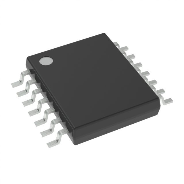
The CDCE913PWRG4 is a Spread Spectrum Clock Driver IC manufactured by Texas Instruments, designed for applications requiring programmable clock generation up to 230MHz with integrated PLL and bypass functionality. This device operates across dual voltage supply ranges (1.7V–1.9V and 2.3V–3.6V) and is packaged in a 14-TSSOP surface mount configuration.
The CDCE913PWRG4 has been discontinued at DiGi Electronics. Identifying equivalent substitute parts ensures design continuity and maintains supply chain reliability for existing applications and new production runs.
Substiute Parts
Key Parameters
| Parameter | Value |
|---|---|
| Manufacturer | Texas Instruments |
| Category | Clock/Timing |
| Type | Spread Spectrum Clock Driver |
| Frequency - Max | 230MHz |
| Voltage - Supply | 1.7V ~ 1.9V, 2.3V ~ 3.6V |
| Operating Temperature | -40°C ~ 85°C |
| Package / Case | 14-TSSOP (0.173", 4.40mm Width) |
| Mounting Type | Surface Mount |
| PLL | Yes with Bypass |
| Input | LVCMOS, Crystal |
| Output | LVCMOS |
| Number of Circuits | 1 |
| Ratio - Input:Output | 1:3 |
| Divider/Multiplier | Yes/Yes |
| RoHS Status | ROHS3 Compliant |
| MSL Rating | 1 (Unlimited) |
Substitute Part Grouping Explanation
Substitution eligibility for the CDCE913PWRG4 is determined by strict equivalence across the following critical parameters:
- Maximum frequency: 230MHz
- Supply voltage ranges: 1.7V–1.9V and 2.3V–3.6V
- Package type: 14-TSSOP surface mount
- PLL configuration: Yes with Bypass
- Input/Output signal types: LVCMOS and Crystal input, LVCMOS output
- Divider and Multiplier functionality: Both present
- Compliance certifications: ROHS3, MSL Level 1
The CDCE913PWR meets all these criteria and qualifies as a parametric equivalent. The primary distinction between the main part and substitute is product status and packaging format availability.
Parameter Comparison
| Parameter | CDCE913PWRG4 | CDCE913PWR |
|---|---|---|
| Manufacturer | Texas Instruments | Texas Instruments |
| Base Product Number | CDCE913 | CDCE913 |
| Type | Spread Spectrum Clock Driver | Spread Spectrum Clock Driver |
| Frequency - Max | 230MHz | 230MHz |
| Voltage - Supply | 1.7V ~ 1.9V, 2.3V ~ 3.6V | 1.7V ~ 1.9V, 2.3V ~ 3.6V |
| Operating Temperature | -40°C ~ 85°C | -40°C ~ 85°C |
| Package / Case | 14-TSSOP (0.173", 4.40mm Width) | 14-TSSOP (0.173", 4.40mm Width) |
| Mounting Type | Surface Mount | Surface Mount |
| PLL | Yes with Bypass | Yes with Bypass |
| Input | LVCMOS, Crystal | LVCMOS, Crystal |
| Output | LVCMOS | LVCMOS |
| Number of Circuits | 1 | 1 |
| Ratio - Input:Output | 1:3 | 1:3 |
| Divider/Multiplier | Yes/Yes | Yes/Yes |
| RoHS Status | ROHS3 Compliant | ROHS3 Compliant |
| MSL Rating | 1 (Unlimited) | 1 (Unlimited) |
| Product Status | Discontinued at DiGi Electronics | Active |
| Packaging Format | Tape & Reel | Cut Tape (CT) & Digi-Reel® |
Engineering Selection Recommendations
The CDCE913PWR is the direct parametric equivalent for the discontinued CDCE913PWRG4. Both parts share identical electrical specifications, thermal operating range, and package geometry. The CDCE913PWR maintains active product status with higher inventory availability (25,100 units in stock versus 2,260 units for the main part), ensuring supply chain continuity.
Both parts carry ROHS3 compliance and MSL Level 1 rating, meeting environmental and moisture sensitivity requirements for standard manufacturing processes. The CDCE913PWR is available in Cut Tape and Digi-Reel packaging formats, providing flexibility for both prototype and production volume requirements.
For new designs or production transitions, the CDCE913PWR is the appropriate selection. For existing applications currently using CDCE913PWRG4, direct substitution with CDCE913PWR requires no circuit modifications or design validation beyond standard component qualification procedures.
Frequently Asked Questions (FAQ)
Q: Can CDCE913PWR directly replace CDCE913PWRG4 in existing designs?
A: Yes. Both parts are parametrically identical across all electrical, thermal, and mechanical specifications. No circuit modifications are required for direct substitution.
Q: What is the difference between CDCE913PWRG4 and CDCE913PWR?
A: The primary differences are product status and packaging availability. CDCE913PWRG4 is discontinued; CDCE913PWR is active. CDCE913PWR offers Cut Tape and Digi-Reel packaging options, while CDCE913PWRG4 was supplied in Tape & Reel format.
Q: Are there any compliance or certification differences?
A: No. Both parts carry identical ROHS3 compliance and MSL Level 1 ratings. Environmental and regulatory certifications are equivalent.
Q: What supply voltage ranges does this clock driver support?
A: The CDCE913PWR operates across two voltage ranges: 1.7V to 1.9V and 2.3V to 3.6V. Dual-range operation allows flexibility in mixed-voltage system designs.
Q: What is the maximum output frequency?
A: The maximum frequency is 230MHz. The device includes integrated divider and multiplier functions for flexible clock generation within this specification.
Q: Is the 14-TSSOP package suitable for high-density PCB layouts?
A: Yes. The 14-TSSOP package measures 0.173 inches (4.40mm) in width and is optimized for surface mount assembly on standard PCB equipment. MSL Level 1 rating permits unlimited shelf life storage without moisture bake-out requirements.
Q: Can this device accept both crystal and LVCMOS inputs?
A: Yes. The CDCE913PWR supports both LVCMOS and crystal input signals, with integrated PLL and bypass functionality for flexible clock source configuration.
Alternative Parts

SJ6012L2TP
Littelfuse Inc.
6 Alternative Parts

JMK107BBJ476MA-RE
Taiyo Yuden
10 Alternative Parts

GMK107BBJ475MA-T
Taiyo Yuden
5 Alternative Parts
SJ6020N2ARP
Littelfuse Inc.
3 Alternative Parts
SJ6025R2ATP
Littelfuse Inc.
4 Alternative Parts

2474-05L
API Delevan Inc.
1 Alternative Parts

4590R-684K
API Delevan Inc.
1 Alternative Parts

CM6560R-334
API Delevan Inc.
1 Alternative Parts

CM6460-104
API Delevan Inc.
1 Alternative Parts

5526-12
API Delevan Inc.
1 Alternative Parts