


Request Quote
(Ships tomorrow)
CD19FD751FO3 750 pF Mica Capacitor Equivalent & Substitute Parts
Part Overview
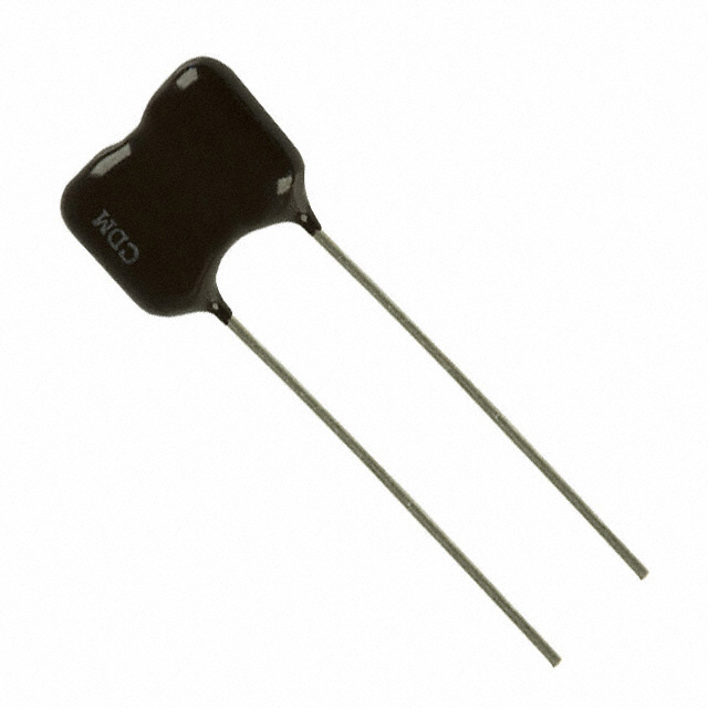
The CD19FD751FO3 is a 750 pF mica capacitor manufactured by Cornell Dubilier Electronics (CDE) in the CD19 series. This through-hole radial capacitor operates at 500 V rated voltage with ±1% tolerance and is designed for general-purpose applications across an operating temperature range of -55°C to 125°C. The part is currently active in production with 692 pieces available in new original stock.
Identification of equivalent and substitute parts is necessary to ensure design flexibility, manage supply chain continuity, and accommodate varying compliance requirements across different manufacturing and regulatory environments.
Substiute Parts
Key Parameters
| Parameter | Value |
|---|---|
| Capacitance | 750 pF |
| Tolerance | ±1% |
| Voltage - Rated | 500 V |
| Dielectric Material | Mica |
| Mounting Type | Through Hole |
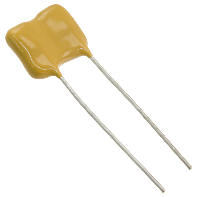
| Package / Case | Radial |
| Lead Spacing | 0.343" (8.70 mm) |
| Operating Temperature Range | -55°C to 125°C |
| Size / Dimension | 0.650" L x 0.209" W (16.50 mm x 5.30 mm) |
| Height - Seated (Max) | 0.512" (13.00 mm) |
| Series | CD19 |
| Manufacturer | Cornell Dubilier Electronics (CDE) |
Substitute Part Grouping Explanation
Substitution eligibility for the CD19FD751FO3 is determined by strict equivalence across the following critical parameters:
Electrical Parameters: Capacitance value (750 pF), tolerance (±1%), and rated voltage (500 V) must be identical. The dielectric material (mica) is fixed and non-negotiable for this product category.
Mechanical Parameters: Mounting type (through hole), package configuration (radial), lead spacing (0.343" / 8.70 mm), physical dimensions (0.650" L x 0.209" W), and maximum seated height (0.512") must match exactly to ensure PCB compatibility and assembly feasibility.
Environmental Parameters: Operating temperature range (-55°C to 125°C) must be maintained.
Series Designation: Parts must belong to the CD19 series from Cornell Dubilier Electronics.
Parts meeting all these criteria are classified as parametric equivalents and direct substitutes. Compliance certifications (RoHS, REACH, ECCN) and packaging formats may vary without affecting functional substitutability.
Parameter Comparison
| Parameter | CD19FD751FO3 | CD19FD751FO3F | Match Status |
|---|---|---|---|
| Manufacturer Part Number | CD19FD751FO3 | CD19FD751FO3F | Variant |
| Manufacturer | Cornell Dubilier Electronics (CDE) | Cornell Dubilier Electronics (CDE) | Identical |
| Series | CD19 | CD19 | Identical |
| Capacitance | 750 pF | 750 pF | Identical |
| Tolerance | ±1% | ±1% | Identical |
| Voltage - Rated | 500 V | 500 V | Identical |
| Dielectric Material | Mica | Mica | Identical |
| Operating Temperature | -55°C to 125°C | -55°C to 125°C | Identical |
| Mounting Type | Through Hole | Through Hole | Identical |
| Package / Case | Radial | Radial | Identical |
| Lead Spacing | 0.343" (8.70 mm) | 0.343" (8.70 mm) | Identical |
| Size / Dimension | 0.650" L x 0.209" W (16.50 mm x 5.30 mm) | 0.650" L x 0.209" W (16.50 mm x 5.30 mm) | Identical |
| Height - Seated (Max) | 0.512" (13.00 mm) | 0.512" (13.00 mm) | Identical |
| Product Status | Active | Active | Identical |
| RoHS Status | RoHS non-compliant | ROHS3 Compliant | Different |
| REACH Status | REACH Affected | REACH Unaffected | Different |
| Inventory | 692 Pcs | 873 Pcs | Different |
Engineering Selection Recommendations
CD19FD751FO3F as Primary Substitute: The CD19FD751FO3F is a direct parametric equivalent to the CD19FD751FO3. All electrical, mechanical, and environmental specifications are identical. The primary distinction is regulatory compliance status: CD19FD751FO3F is ROHS3 compliant and REACH unaffected, whereas the original part is RoHS non-compliant and REACH affected.
Selection Criteria:
For applications subject to RoHS3 or REACH regulatory requirements, CD19FD751FO3F is the appropriate selection. Both parts are active in production and available in adequate stock quantities.
For applications with no regulatory compliance constraints, either part may be selected based on availability and supply chain considerations.
Both parts carry identical ECCN (EAR99) and HTSUS (8532.29.0020) classifications, indicating equivalent export and tariff treatment.
Frequently Asked Questions (FAQ)
Q: Can CD19FD751FO3F be used as a direct replacement for CD19FD751FO3 in existing designs?
A: Yes. CD19FD751FO3F is a parametric equivalent with identical electrical, mechanical, and environmental specifications. No circuit redesign or PCB layout modification is required. The parts are pin-compatible and functionally interchangeable.
Q: What is the difference between CD19FD751FO3 and CD19FD751FO3F?
A: The parts are electrically and mechanically identical. The suffix "F" in CD19FD751FO3F indicates ROHS3 compliance and REACH unaffected status. The original CD19FD751FO3 is RoHS non-compliant and REACH affected. Selection depends on regulatory requirements applicable to the end application.
Q: Are the physical dimensions and lead spacing identical between these parts?
A: Yes. Both parts have identical dimensions (0.650" L x 0.209" W), lead spacing (0.343" / 8.70 mm), and maximum seated height (0.512" / 13.00 mm). PCB footprints and assembly processes are identical.
Q: What is the operating temperature range for these capacitors?
A: Both CD19FD751FO3 and CD19FD751FO3F operate across -55°C to 125°C. This range applies to all electrical and mechanical specifications.
Q: Are these parts suitable for high-voltage applications?
A: Both parts are rated for 500 V. Applications requiring higher voltage ratings require alternative part selection outside this product family.
Q: What does the ±1% tolerance specification mean?
A: The ±1% tolerance indicates that the actual capacitance value will be within 750 pF ± 7.5 pF (range: 742.5 pF to 757.5 pF). This tight tolerance is characteristic of mica dielectric capacitors and is suitable for precision circuit applications.
Q: Can these radial capacitors be mounted in any orientation on the PCB?
A: Radial capacitors have two leads extending from the same end of the component body. Orientation on the PCB is determined by polarity markings and circuit requirements. Consult the specific circuit schematic for correct lead assignment.
Alternative Parts

SJ6012L2TP
Littelfuse Inc.
6 Alternative Parts

JMK107BBJ476MA-RE
Taiyo Yuden
10 Alternative Parts

GMK107BBJ475MA-T
Taiyo Yuden
5 Alternative Parts
SJ6020N2ARP
Littelfuse Inc.
3 Alternative Parts
SJ6025R2ATP
Littelfuse Inc.
4 Alternative Parts

2474-05L
API Delevan Inc.
1 Alternative Parts

4590R-684K
API Delevan Inc.
1 Alternative Parts

CM6560R-334
API Delevan Inc.
1 Alternative Parts

CM6460-104
API Delevan Inc.
1 Alternative Parts

5526-12
API Delevan Inc.
1 Alternative Parts