


Request Quote
(Ships tomorrow)
Equivalent & Substitute Parts for CA.50 RF Antenna
Part Overview
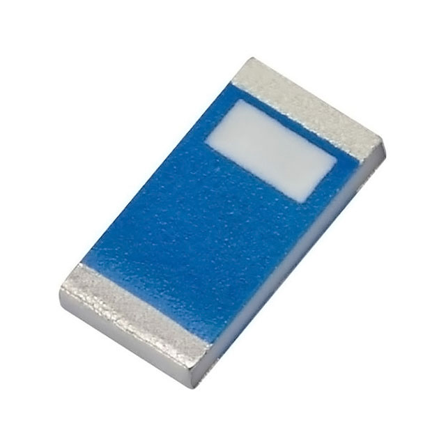
The CA.50 is a 5.5GHz WLAN chip RF antenna manufactured by Taoglas Limited, designed for surface mount applications in wireless local area network systems. This component operates across the 5.15GHz to 5.9GHz frequency band with a gain of 3.4dBi and a maximum power rating of 50W. The product is currently classified as obsolete, necessitating identification of functionally compatible alternatives for ongoing design requirements and production continuity.
Substiute Parts
Key Parameters
| Parameter | Value |
|---|---|
| Manufacturer Part Number | CA.50 |
| Manufacturer | Taoglas Limited |
| RF Family/Standard | WiFi |
| Frequency (Center/Band) | 5.5GHz |
| Frequency Range | 5.15GHz ~ 5.9GHz |
| Antenna Type | Chip |
| Gain | 3.4dBi |
| VSWR | 2 |
| Return Loss | -17dB |
| Power - Max | 50W |
| Mounting Type | Surface Mount |
| Height (Max) | 0.020" (0.50mm) |
| Termination | Solder |
| Product Status | Obsolete |
| RoHS Status | ROHS3 Compliant |
| MSL Rating | 3 (168 Hours) |
Substitute Part Grouping Explanation
Substitution eligibility for the CA.50 is determined by the following critical parameters:
Mandatory Compatibility Criteria:
- Antenna Type: Chip configuration
- Mounting Type: Surface Mount
- Termination: Solder
- Height (Max): 0.020" (0.50mm)
- Frequency Coverage: Must include 5.15GHz ~ 5.9GHz band
- RF Standard: WiFi/WLAN support
Performance Parameters:
- Gain: 3.4dBi (reference value)
- VSWR: 2 (reference value)
- Return Loss: -17dB (reference value)
- Power Rating: 50W maximum
The WLA.10 qualifies as a substitute part because it maintains identical physical form factor (chip antenna, surface mount, solder termination, 0.50mm height), operates within the required 5.15GHz ~ 5.85GHz frequency range, and provides multi-band functionality including the primary 5.5GHz WiFi band. The WLA.10 is currently in active production status, ensuring supply chain continuity.
Parameter Comparison
| Parameter | CA.50 (Main Part) | WLA.10 (Substitute) |
|---|---|---|
| Manufacturer | Taoglas Limited | Taoglas Limited |
| Antenna Type | Chip | Chip |
| Mounting Type | Surface Mount | Surface Mount |
| Termination | Solder | Solder |
| Height (Max) | 0.020" (0.50mm) | 0.020" (0.50mm) |
| Frequency (Center/Band) | 5.5GHz | 1.575GHz, 2.4GHz, 5.5GHz |
| Frequency Range | 5.15GHz ~ 5.9GHz | 1.575GHz, 2.4GHz ~ 2.5GHz, 5.15GHz ~ 5.85GHz |
| Number of Bands | 1 | 3 |
| Gain | 3.4dBi | 1.8dBi |
| VSWR | 2 | Not specified |
| Return Loss | -17dB | -10dB |
| Power - Max | 50W | 2W |
| RF Family/Standard | WiFi | 802.15.4, Bluetooth, Navigation, WiFi |
| Product Status | Obsolete | Active |
| RoHS Status | ROHS3 Compliant | ROHS3 Compliant |
| MSL Rating | 3 (168 Hours) | 3 (168 Hours) |
Engineering Selection Recommendations
The WLA.10 serves as the primary substitute for the obsolete CA.50 based on the following engineering criteria:
Product Status & Supply Continuity: The WLA.10 maintains active production status with 2927 units in current inventory, whereas the CA.50 is obsolete with limited remaining stock (847 units). Selection of the WLA.10 ensures long-term component availability and supply chain stability.
Regulatory Compliance: Both components maintain ROHS3 compliance and REACH unaffected status, satisfying environmental and regulatory requirements. Moisture sensitivity levels are identical at MSL 3 (168 Hours), ensuring equivalent handling and storage protocols.
Physical & Electrical Compatibility: The WLA.10 maintains identical physical dimensions (0.50mm maximum height) and mounting characteristics (surface mount, solder termination), enabling direct PCB layout compatibility without redesign. Both components operate within overlapping frequency ranges covering the 5.15GHz ~ 5.85GHz WiFi band.
Performance Trade-offs: The WLA.10 provides multi-band functionality (1.575GHz, 2.4GHz, 5.5GHz) compared to the single-band CA.50. However, the WLA.10 exhibits lower gain (1.8dBi versus 3.4dBi) and reduced maximum power rating (2W versus 50W). These differences require circuit-level evaluation to confirm suitability for specific power and gain requirements.
Frequently Asked Questions (FAQ)
Q: Can the WLA.10 directly replace the CA.50 without PCB modifications?
A: Physical form factor compatibility is confirmed. Both components share identical mounting type (surface mount), termination method (solder), and maximum height (0.50mm). PCB layout modifications are not required for mechanical integration. However, circuit performance must be evaluated due to differences in gain (3.4dBi vs. 1.8dBi) and maximum power rating (50W vs. 2W).
Q: What are the key differences between CA.50 and WLA.10?
A: The primary differences are: (1) Product Status—CA.50 is obsolete while WLA.10 is active; (2) Frequency Coverage—CA.50 operates single-band at 5.5GHz, WLA.10 operates tri-band at 1.575GHz, 2.4GHz, and 5.5GHz; (3) Gain—CA.50 provides 3.4dBi versus WLA.10 at 1.8dBi; (4) Power Rating—CA.50 rated 50W maximum versus WLA.10 at 2W maximum; (5) Return Loss—CA.50 at -17dB versus WLA.10 at -10dB.
Q: Is the WLA.10 suitable for high-power WiFi applications?
A: The WLA.10 has a maximum power rating of 2W, compared to the CA.50 at 50W. Applications requiring power levels exceeding 2W require alternative component selection or circuit redesign to operate within the WLA.10 power specification.
Q: Are there packaging differences between these components?
A: The CA.50 is specified with packaging designation "-" (not detailed). The WLA.10 is supplied in Tape & Reel (TR) packaging. Verify packaging compatibility with assembly equipment and procurement requirements.
Q: Do both components meet the same environmental and regulatory standards?
A: Yes. Both CA.50 and WLA.10 are ROHS3 compliant, REACH unaffected, and carry identical MSL ratings of 3 (168 Hours). Handling, storage, and soldering protocols are equivalent.
Q: What is the impact of lower gain on system performance?
A: The WLA.10 gain of 1.8dBi is 1.6dBi lower than the CA.50 at 3.4dBi. This reduction affects antenna efficiency and received signal strength. System-level link budget analysis is required to determine if the lower gain is acceptable for target coverage and data rate requirements.
Alternative Parts

SJ6012L2TP
Littelfuse Inc.
6 Alternative Parts

JMK107BBJ476MA-RE
Taiyo Yuden
10 Alternative Parts

GMK107BBJ475MA-T
Taiyo Yuden
5 Alternative Parts
SJ6020N2ARP
Littelfuse Inc.
3 Alternative Parts
SJ6025R2ATP
Littelfuse Inc.
4 Alternative Parts

2474-05L
API Delevan Inc.
1 Alternative Parts

4590R-684K
API Delevan Inc.
1 Alternative Parts

CM6560R-334
API Delevan Inc.
1 Alternative Parts

CM6460-104
API Delevan Inc.
1 Alternative Parts

5526-12
API Delevan Inc.
1 Alternative Parts