


Request Quote
(Ships tomorrow)
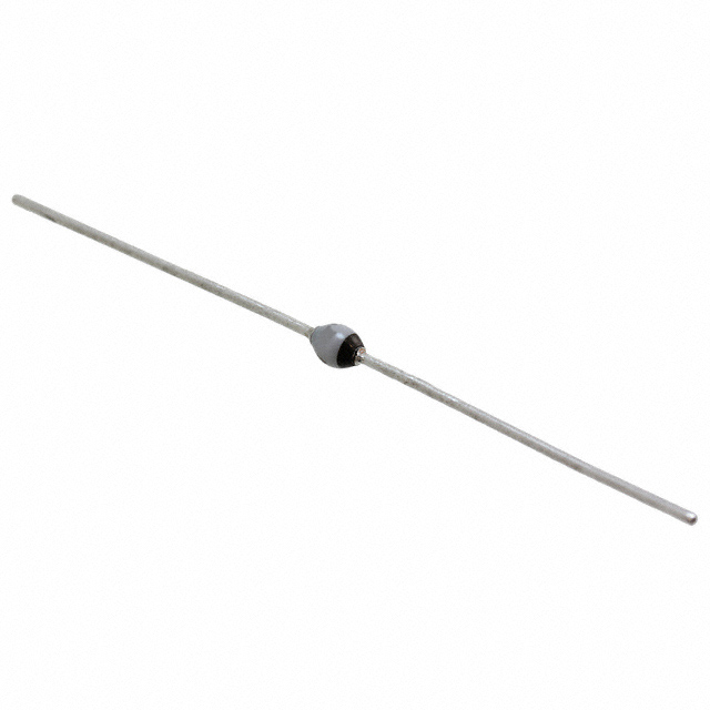
BZX79-B22,113 Equivalent & Substitute Parts
Part Overview
The BZX79-B22,113 is a through-hole zener diode manufactured by Nexperia USA Inc., rated at 22 V nominal zener voltage with 400 mW maximum power dissipation. The device is packaged in DO-204AH (DO-35) axial configuration and is classified as Active product status. This component is used in voltage regulation and protection circuits where precise voltage reference and transient suppression are required. Equivalent and substitute parts are identified to support procurement flexibility, inventory management, and design continuity when the primary part becomes unavailable or when alternative packaging or performance characteristics are acceptable within application requirements.
Substiute Parts
Key Parameters
| Parameter | Value | Unit |
|---|---|---|
| Voltage - Zener (Nom) | 22 | V |
| Tolerance | ±2% | — |
| Power - Max | 400 | mW |
| Impedance (Max) | 55 | Ohms |
| Current - Reverse Leakage @ Vr | 50 nA @ 15.4 V | — |
| Voltage - Forward (Vf) (Max) @ If | 900 mV @ 10 mA | — |
| Operating Temperature Range | -65 to 200 | °C |
| Mounting Type | Through Hole | — |
| Package / Case | DO-204AH, DO-35, Axial | — |
| RoHS Status | ROHS3 Compliant | — |
Substitute Part Grouping Explanation
Substitution of zener diodes is determined by the following critical parameters: nominal zener voltage (Vz), maximum power dissipation rating (P-Max), voltage tolerance, operating temperature range, and package compatibility. The BZX79-B22,113 operates at 22 V with ±2% tolerance, 400 mW power rating, and -65°C to 200°C temperature range in DO-35 axial through-hole packaging.
Substitute parts are classified into two categories:
Parametric Equivalent: Parts with identical or tighter electrical specifications and the same package type, allowing direct substitution without circuit modification.
Similar Parts: Components with the same nominal zener voltage but differing in power rating, tolerance, impedance, or package configuration. These parts require application-level verification to confirm suitability based on circuit power dissipation requirements and thermal management capabilities.
Parameter Comparison
| Parameter | BZX79-B22,113 (Main) | BZX79-B22,143 (Parametric Equivalent) | 1N5251B-TAP (Similar) | BZT03C22-TR (Similar) |
|---|---|---|---|---|
| Manufacturer | Nexperia USA Inc. | NXP USA Inc. | Vishay General Semiconductor - Diodes Division | Vishay General Semiconductor - Diodes Division |
| Voltage - Zener (Nom) | 22 V | 22 V | 22 V | 22 V |
| Tolerance | ±2% | ±2% | ±5% | ±5.68% |
| Power - Max | 400 mW | 400 mW | 500 mW | 1.3 W |
| Impedance (Max) | 55 Ohms | 55 Ohms | 29 Ohms | 15 Ohms |
| Current - Reverse Leakage @ Vr | 50 nA @ 15.4 V | 50 nA @ 15.4 V | 100 nA @ 17 V | 1 µA @ 16 V |
| Voltage - Forward (Vf) (Max) @ If | 900 mV @ 10 mA | 900 mV @ 10 mA | 1.1 V @ 200 mA | 1.2 V @ 500 mA |
| Operating Temperature Range | -65 to 200°C | -65 to 200°C | 175°C (Max) | 175°C (TJ) |
| Mounting Type | Through Hole | Through Hole | Through Hole | Through Hole |
| Package / Case | DO-204AH, DO-35, Axial | DO-204AH, DO-35, Axial | DO-204AH, DO-35, Axial | SOD-57, Axial |
| Packaging Type | Cut Tape (CT) | Bulk | Cut Tape (CT) | Cut Tape (CT) |
| RoHS Status | ROHS3 Compliant | ROHS3 Compliant | ROHS3 Compliant | ROHS3 Compliant |
| Product Status | Active | Active | Active | Active |
Engineering Selection Recommendations
BZX79-B22,143 (Parametric Equivalent): This part is a direct parametric equivalent to the BZX79-B22,113, sharing identical electrical specifications including 22 V nominal voltage, ±2% tolerance, 400 mW power rating, 55 Ohms maximum impedance, and -65°C to 200°C operating temperature range. Both parts are manufactured by NXP (Nexperia USA Inc. and NXP USA Inc. are related entities) and packaged in DO-204AH (DO-35) axial configuration. The primary difference is packaging format: BZX79-B22,143 is supplied in Bulk packaging versus Cut Tape for the main part. Both are ROHS3 Compliant and Active status. This part is suitable for direct substitution in applications where bulk packaging is acceptable.
1N5251B-TAP (Similar Part): This Vishay component maintains the 22 V nominal zener voltage but differs in several parameters. Power rating is increased to 500 mW (25% higher than the main part), impedance is reduced to 29 Ohms (lower than 55 Ohms), and tolerance is relaxed to ±5% (versus ±2%). Operating temperature maximum is 175°C, which is lower than the main part's 200°C upper limit. The device is qualified to AEC-Q101 automotive standard and packaged in DO-204AH (DO-35) axial configuration. This part is suitable for applications where higher power dissipation capability is beneficial and tighter voltage tolerance is not required.
BZT03C22-TR (Similar Part): This Vishay TVS diode operates at 22 V nominal voltage but is packaged in SOD-57 axial configuration, which differs from the DO-35 package of the main part. Power rating is significantly higher at 1.3 W (more than three times the main part), impedance is lower at 15 Ohms, and tolerance is ±5.68%. Operating temperature is 175°C maximum. The SOD-57 package requires different PCB footprint and lead spacing compared to DO-35. This part is suitable for high-power applications or where enhanced transient suppression is required, provided PCB layout accommodates the different package geometry.
All substitute parts maintain ROHS3 compliance and Active product status, supporting regulatory and supply chain continuity requirements.
Frequently Asked Questions (FAQ)
Q: Can BZX79-B22,143 be used as a direct replacement for BZX79-B22,113?
A: Yes. BZX79-B22,143 is a parametric equivalent with identical electrical specifications (22 V, ±2%, 400 mW, 55 Ohms impedance) and the same DO-35 axial package. The only difference is bulk packaging versus cut tape. Direct substitution is supported without circuit modification.
Q: What are the key differences between the main part and 1N5251B-TAP?
A: Both operate at 22 V nominal voltage in DO-35 packages. Key differences are: 1N5251B-TAP has 500 mW power rating (versus 400 mW), ±5% tolerance (versus ±2%), 29 Ohms impedance (versus 55 Ohms), and 175°C maximum operating temperature (versus 200°C). The 1N5251B-TAP is AEC-Q101 qualified for automotive applications.
Q: Why does BZT03C22-TR have a different package (SOD-57) compared to the main part (DO-35)?
A: BZT03C22-TR is designed as a higher-power TVS diode with 1.3 W rating. The SOD-57 package provides improved thermal characteristics for higher power dissipation. SOD-57 has different lead spacing and PCB footprint than DO-35, requiring layout verification before substitution.
Q: Can I use 1N5251B-TAP in a circuit designed for BZX79-B22,113 if the circuit only dissipates 300 mW?
A: Yes, from a power dissipation perspective. However, the ±5% tolerance of 1N5251B-TAP (versus ±2% for the main part) may affect voltage regulation accuracy. Verify that the application's voltage tolerance specification accommodates the wider tolerance range.
Q: Are all substitute parts RoHS3 compliant?
A: Yes. BZX79-B22,143, 1N5251B-TAP, and BZT03C22-TR are all ROHS3 Compliant, matching the compliance status of the main part BZX79-B22,113.
Q: What is the operating temperature limitation when using 1N5251B-TAP or BZT03C22-TR?
A: Both parts have a maximum operating temperature of 175°C, which is 25°C lower than the main part's 200°C upper limit. Applications requiring operation above 175°C must use BZX79-B22,113 or BZX79-B22,143.
Q: Does impedance difference affect circuit performance?
A: Impedance affects voltage regulation under load changes. BZX79-B22,113 and BZX79-B22,143 have 55 Ohms impedance. 1N5251B-TAP has 29 Ohms (lower), and BZT03C22-TR has 15 Ohms (significantly lower). Lower impedance provides better voltage stability under transient conditions. Verify impedance requirements for your specific application.
Q: Can BZT03C22-TR be used in a through-hole PCB designed for DO-35 packages?
A: No. BZT03C22-TR uses SOD-57 package with different lead spacing and footprint. PCB layout modification is required. Physical verification of lead positioning and hole spacing is necessary before substitution.
Alternative Parts

SJ6012L2TP
Littelfuse Inc.
6 Alternative Parts

JMK107BBJ476MA-RE
Taiyo Yuden
10 Alternative Parts

GMK107BBJ475MA-T
Taiyo Yuden
5 Alternative Parts
SJ6020N2ARP
Littelfuse Inc.
3 Alternative Parts
SJ6025R2ATP
Littelfuse Inc.
4 Alternative Parts

2474-05L
API Delevan Inc.
1 Alternative Parts

4590R-684K
API Delevan Inc.
1 Alternative Parts

CM6560R-334
API Delevan Inc.
1 Alternative Parts

CM6460-104
API Delevan Inc.
1 Alternative Parts

5526-12
API Delevan Inc.
1 Alternative Parts