


Request Quote
(Ships tomorrow)
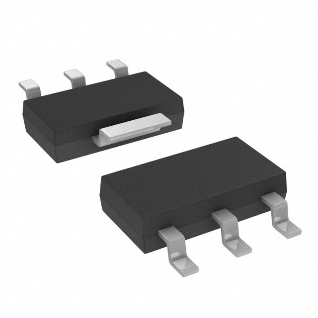
BSP613P P-Channel MOSFET 60V 2.9A Equivalent & Substitute Parts
Part Overview
The BSP613P is a P-Channel enhancement-mode MOSFET manufactured by Infineon Technologies, designed for surface mount applications in the SOT223-4 package. This device operates at 60V drain-to-source voltage with a continuous drain current rating of 2.9A at 25°C and maximum power dissipation of 1.8W. The BSP613P is classified as obsolete product status, making identification of active equivalent and substitute parts essential for ongoing design support and procurement continuity. Equivalent parts must maintain identical electrical performance within the specified parameter ranges while substitute parts may offer enhanced performance characteristics within compatible package and voltage specifications.
Substiute Parts
Key Parameters
| Parameter | Value | Unit |
|---|---|---|
| FET Type | P-Channel | — |
| Drain to Source Voltage (Vdss) | 60 | V |
| Continuous Drain Current (Id) @ 25°C | 2.9 | A |
| On-State Resistance (Rds On) @ 2.9A, 10V | 130 | mOhm |
| Gate Threshold Voltage (Vgs(th)) @ 1mA | 4 | V |
| Gate Charge (Qg) @ 10V | 33 | nC |
| Input Capacitance (Ciss) @ 25V | 875 | pF |
| Maximum Gate Voltage (Vgs) | ±20 | V |
| Power Dissipation (Max) | 1.8 | W |
| Operating Temperature Range | -55 to 150 | °C |
| Package Type | SOT223-4 (TO-261-4, TO-261AA) | — |
| Mounting Type | Surface Mount | — |
Substitute Part Grouping Explanation
Substitution logic for the BSP613P is based on the following critical parameters that must be maintained or exceeded:
Electrical Compatibility Criteria:
- Drain-to-source voltage (Vdss) must equal or exceed 60V
- Continuous drain current (Id) must equal or exceed 2.9A at 25°C
- Gate threshold voltage (Vgs(th)) must be compatible with 10V drive voltage
- Maximum gate voltage (Vgs) must support ±20V operation
- Operating temperature range must encompass -55°C to 150°C
Package and Mechanical Compatibility:
- Surface mount technology required
- SOT223 package family (SOT223-3 or SOT223-4 variants acceptable)
- TO-261 series package designation
Compliance and Status:
- Active product status preferred for long-term availability
- RoHS3 compliance required for new designs
- Moisture sensitivity level MSL 1 (unlimited shelf life)
The substitute parts listed below meet or exceed these criteria while offering enhanced performance in specific parameters such as increased drain current (3A), improved on-state resistance, or reduced gate charge.
Parameter Comparison
| Parameter | BSP613P (Main) | BSP613PH6327XTSA1 (Equivalent) | PJW3P06A_R2_00001 (Substitute) | PJW3P06A-AU_R2_000A1 (Substitute) | ZXMP6A17GTA (Substitute) |
|---|---|---|---|---|---|
| Manufacturer | Infineon Technologies | Infineon Technologies | Panjit International Inc. | Panjit International Inc. | Diodes Incorporated |
| Product Status | Obsolete | Active | Active | Active | Active |
| FET Type | P-Channel | P-Channel | P-Channel | P-Channel | P-Channel |
| Vdss (V) | 60 | 60 | 60 | 60 | 60 |
| Id @ 25°C (A) | 2.9 | 2.9 | 3 | 3 | 3 |
| Rds On @ 10V (mOhm) | 130 @ 2.9A | 130 @ 2.9A | 190 @ 2A | 170 @ 2A | 125 @ 2.2A |
| Vgs(th) @ Id (V) | 4 @ 1mA | 4 @ 1mA | 2.5 @ 250µA | 2.5 @ 250µA | 1 @ 250µA |
| Qg @ 10V (nC) | 33 | 33 | 8.3 | 8.3 | 17.7 |
| Ciss @ Vds (pF) | 875 @ 25V | 875 @ 25V | 430 @ 30V | 430 @ 30V | 637 @ 30V |
| Vgs (Max) (V) | ±20 | ±20 | ±20 | ±20 | ±20 |
| Power Dissipation (W) | 1.8 | 1.8 | 3.1 | 3.1 | 2 |
| Operating Temp (°C) | -55 to 150 | -55 to 150 | -55 to 150 | -55 to 150 | -55 to 150 |
| Package | SOT223-4 | SOT223-4 | SOT223 | SOT223 | SOT223-3 |
| RoHS Status | Non-compliant | ROHS3 Compliant | ROHS3 Compliant | ROHS3 Compliant | ROHS3 Compliant |
| Automotive Grade | — | — | — | AEC-Q101 | — |
Engineering Selection Recommendations
BSP613PH6327XTSA1 (Infineon Technologies) — Direct Equivalent
This part is the recommended first choice for direct replacement of the obsolete BSP613P. The BSP613PH6327XTSA1 maintains identical electrical specifications across all critical parameters including Vdss (60V), Id (2.9A), Rds On (130mOhm @ 2.9A, 10V), gate charge (33nC), and input capacitance (875pF). The primary advantage is active product status with 69,376 pieces in stock, ensuring procurement continuity. This part achieves ROHS3 compliance, addressing environmental regulatory requirements that the obsolete BSP613P does not meet. The SOT223-4 package is identical to the original design, requiring no PCB layout modifications. Recommended for direct substitution in existing designs without circuit re-evaluation.
PJW3P06A_R2_00001 (Panjit International Inc.) — Performance Substitute
This part offers enhanced performance characteristics suitable for designs requiring improved current handling or thermal performance. The PJW3P06A_R2_00001 provides 3A continuous drain current (versus 2.9A), increased power dissipation capability (3.1W versus 1.8W), and significantly reduced gate charge (8.3nC versus 33nC). The on-state resistance is higher at 190mOhm @ 2A compared to 130mOhm @ 2.9A, but the lower gate threshold voltage (2.5V versus 4V) enables faster switching response. This part is active with 25,300 units in stock and achieves ROHS3 compliance. The SOT223 package is mechanically compatible. Suitable for new designs or upgrades where improved thermal margin and switching speed are beneficial.
PJW3P06A-AU_R2_000A1 (Panjit International Inc.) — Automotive-Qualified Substitute
This variant of the PJW3P06A series includes AEC-Q101 automotive qualification, making it suitable for automotive and industrial applications requiring functional safety compliance. Electrical specifications are identical to PJW3P06A_R2_00001 (3A, 3.1W, 8.3nC gate charge). The automotive qualification adds design assurance for mission-critical applications. Inventory availability is lower at 7,912 units. Recommended for automotive designs or applications requiring automotive-grade component certification.
ZXMP6A17GTA (Diodes Incorporated) — Performance Substitute
The ZXMP6A17GTA from Diodes Incorporated provides the lowest on-state resistance (125mOhm @ 2.2A, 10V) among all substitute options, delivering superior thermal efficiency. This part supports 3A continuous drain current and 2W power dissipation. The gate threshold voltage is significantly lower (1V versus 4V), enabling operation with reduced drive voltage. Gate charge is moderate at 17.7nC. The SOT223-3 package is mechanically compatible with SOT223-4 designs. This part is active with 45,400 units in stock and achieves ROHS3 compliance. Recommended for designs prioritizing low on-state losses and thermal performance.
Frequently Asked Questions (FAQ)
Q: Can I directly replace BSP613P with BSP613PH6327XTSA1 without circuit modifications?
A: Yes. The BSP613PH6327XTSA1 is a parametric equivalent with identical electrical specifications and package type (SOT223-4). No circuit re-evaluation or PCB layout changes are required. This is the recommended direct replacement for obsolete BSP613P designs.
Q: What are the key differences between the Infineon equivalent and Panjit substitutes?
A: The Infineon BSP613PH6327XTSA1 maintains exact electrical specifications of the original BSP613P. The Panjit PJW3P06A series (both variants) offer higher drain current (3A versus 2.9A), significantly lower gate charge (8.3nC versus 33nC), and lower gate threshold voltage (2.5V versus 4V). These differences result in faster switching response and improved thermal performance but require verification that the lower gate threshold voltage is compatible with your drive circuit.
Q: Is the ZXMP6A17GTA package compatible with SOT223-4 PCB layouts?
A: The ZXMP6A17GTA uses SOT223-3 package while the original BSP613P uses SOT223-4. Both are mechanically compatible with TO-261 series footprints. However, verify that your PCB layout accommodates the SOT223-3 pin configuration. The SOT223-3 package has three leads versus four in SOT223-4, so pin assignment must be confirmed before assembly.
Q: Which substitute part should I select for a new design?
A: For new designs, select based on performance requirements: (1) If thermal margin is critical, choose ZXMP6A17GTA for lowest on-state resistance; (2) If switching speed is important, choose PJW3P06A variants for lowest gate charge; (3) If automotive qualification is required, choose PJW3P06A-AU_R2_000A1. All substitute parts are active, RoHS3 compliant, and available in quantity.
Q: Are all listed parts RoHS3 compliant?
A: The BSP613P (obsolete) is RoHS non-compliant. All active substitute and equivalent parts (BSP613PH6327XTSA1, PJW3P06A_R2_00001, PJW3P06A-AU_R2_000A1, and ZXMP6A17GTA) are ROHS3 compliant, meeting current environmental regulations for new designs and procurement.
Q: What is the impact of different gate threshold voltages on circuit design?
A: Gate threshold voltage (Vgs(th)) determines the minimum gate-source voltage required to turn on the MOSFET. The BSP613P and BSP613PH6327XTSA1 require 4V @ 1mA, while substitutes require 2.5V or 1V @ 250µA. Lower threshold voltages enable operation with reduced drive voltage but may increase susceptibility to parasitic turn-on in high-noise environments. Verify your gate drive circuit can reliably maintain the required Vgs level for your selected part.
Q: Can I use these parts interchangeably in existing inventory?
A: Direct interchange is only recommended between BSP613P and BSP613PH6327XTSA1 due to identical specifications. Substituting with Panjit or Diodes parts requires circuit verification due to differences in gate charge, threshold voltage, and on-state resistance. Mixing parts in the same design is not recommended without documented engineering analysis.
Q: What is the significance of gate charge (Qg) differences?
A: Gate charge determines the energy required to switch the MOSFET and affects switching speed and power dissipation in the gate drive circuit. The BSP613P requires 33nC @ 10V, while Panjit substitutes require only 8.3nC. Lower gate charge reduces switching losses and gate drive power consumption, enabling faster switching frequencies. Verify your gate drive circuit has sufficient current capability for your selected part's gate charge.
Alternative Parts

SJ6012L2TP
Littelfuse Inc.
6 Alternative Parts

JMK107BBJ476MA-RE
Taiyo Yuden
10 Alternative Parts

GMK107BBJ475MA-T
Taiyo Yuden
5 Alternative Parts
SJ6020N2ARP
Littelfuse Inc.
3 Alternative Parts
SJ6025R2ATP
Littelfuse Inc.
4 Alternative Parts

2474-05L
API Delevan Inc.
1 Alternative Parts

4590R-684K
API Delevan Inc.
1 Alternative Parts

CM6560R-334
API Delevan Inc.
1 Alternative Parts

CM6460-104
API Delevan Inc.
1 Alternative Parts

5526-12
API Delevan Inc.
1 Alternative Parts