


Request Quote
(Ships tomorrow)
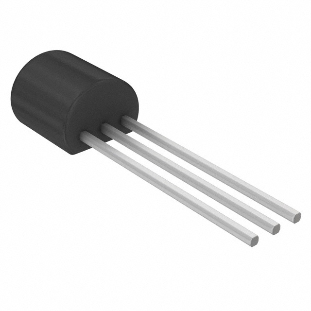
BS170 N-Channel MOSFET 60V 500mA TO-92-3 Equivalent & Substitute Parts
Part Overview
The BS170 is an N-Channel MOSFET manufactured by onsemi, rated for 60V drain-to-source voltage with 500mA continuous drain current at 25°C. The device is housed in a TO-92-3 through-hole package and dissipates a maximum of 830mW. The BS170 maintains Active product status and is RoHS3 compliant. Substitute parts are identified when equivalent electrical performance and mechanical compatibility are required due to inventory constraints, manufacturing discontinuation, or design flexibility within specified parameter tolerances.
Substiute Parts
Key Parameters
| Parameter | Value | Unit |
|---|---|---|
| FET Type | N-Channel | — |
| Technology | MOSFET (Metal Oxide) | — |
| Drain to Source Voltage (Vdss) | 60 | V |
| Current - Continuous Drain (Id) @ 25°C | 500 | mA |
| Rds On (Max) @ Id, Vgs | 5 | Ohm @ 200mA, 10V |
| Vgs(th) (Max) @ Id | 3 | V @ 1mA |
| Power Dissipation (Max) | 830 | mW |
| Operating Temperature Range | -55 to 150 | °C (TJ) |
| Mounting Type | Through Hole | — |
| Package | TO-92-3 (TO-226AA) | — |
Substitute Part Grouping Explanation
Substitute parts for the BS170 are qualified based on the following criteria:
Electrical Compatibility Requirements:
- Drain-to-source voltage (Vdss) must equal or exceed 60V
- FET type must be N-Channel MOSFET (Metal Oxide technology)
- Operating temperature range must encompass -55°C to 150°C
- RoHS3 compliance and REACH unaffected status required
Mechanical Compatibility Requirements:
- Mounting type: Through Hole
- Package: TO-92-3 (TO-226AA)
Performance Considerations:
- Continuous drain current (Id) at 25°C may be lower than the primary part if application requirements permit
- On-resistance (Rds On) characteristics must be documented at specified gate-source voltage and drain current conditions
- Gate-source threshold voltage (Vgs(th)) specifications must be provided
- Power dissipation ratings establish thermal operating envelope
The substitute parts VN10KN3-G and VN2106N3-G meet all electrical and mechanical compatibility criteria. Both devices share identical Vdss (60V), matching package configuration (TO-92-3), and overlapping operating temperature range. Differences in continuous drain current and power dissipation are documented in the parameter comparison table.
Parameter Comparison
| Parameter | BS170 (onsemi) | VN10KN3-G (Microchip) | VN2106N3-G (Microchip) | Unit |
|---|---|---|---|---|
| Manufacturer | onsemi | Microchip Technology | Microchip Technology | — |
| FET Type | N-Channel | N-Channel | N-Channel | — |
| Technology | MOSFET (Metal Oxide) | MOSFET (Metal Oxide) | MOSFET (Metal Oxide) | — |
| Drain to Source Voltage (Vdss) | 60 | 60 | 60 | V |
| Current - Continuous Drain (Id) @ 25°C | 500 (Ta) | 310 (Tj) | 300 (Tj) | mA |
| Drive Voltage (Max Rds On) | 10 | 5, 10 | 5, 10 | V |
| Rds On (Max) @ Id, Vgs | 5 @ 200mA, 10V | 5 @ 500mA, 10V | 4 @ 500mA, 10V | Ohm |
| Vgs(th) (Max) @ Id | 3 @ 1mA | 2.5 @ 1mA | 2.4 @ 1mA | V |
| Vgs (Max) | ±20 | ±30 | ±20 | V |
| Input Capacitance (Ciss) (Max) @ Vds | 40 @ 10V | 60 @ 25V | 50 @ 25V | pF |
| Power Dissipation (Max) | 830 (Ta) | 1 (Tc) | 1 (Tc) | W |
| Operating Temperature Range | -55 to 150 | -55 to 150 | -55 to 150 | °C (TJ) |
| Mounting Type | Through Hole | Through Hole | Through Hole | — |
| Package | TO-92-3 (TO-226AA) | TO-92-3 (TO-226AA) | TO-92-3 (TO-226AA) | — |
| RoHS Status | ROHS3 Compliant | ROHS3 Compliant | ROHS3 Compliant | — |
| REACH Status | REACH Unaffected | REACH Unaffected | REACH Unaffected | — |
| Product Status | Active | Active | Active | — |
Engineering Selection Recommendations
All three devices—BS170, VN10KN3-G, and VN2106N3-G—maintain Active product status and satisfy RoHS3 and REACH compliance requirements. Selection between these parts depends on application-specific current and power dissipation requirements.
BS170 Selection Criteria: The BS170 supports the highest continuous drain current at 500mA and provides 830mW power dissipation capacity. This device is appropriate for applications requiring maximum current handling within the 60V Vdss envelope.
VN10KN3-G Selection Criteria: The VN10KN3-G provides 310mA continuous drain current and 1W power dissipation. This substitute is suitable for applications where drain current requirements do not exceed 310mA and where the increased power dissipation rating (1W vs. 830mW) provides thermal margin.
VN2106N3-G Selection Criteria: The VN2106N3-G provides 300mA continuous drain current and 1W power dissipation. This substitute offers the lowest on-resistance specification (4 Ohm @ 500mA, 10V) among the three devices, making it suitable for applications prioritizing reduced conduction losses where drain current does not exceed 300mA.
All three devices share identical Vdss (60V), operating temperature range (-55°C to 150°C), and TO-92-3 package configuration, ensuring direct mechanical and electrical interchangeability within the specified current and power dissipation parameters.
Frequently Asked Questions (FAQ)
Q: Can the VN10KN3-G or VN2106N3-G be used as direct replacements for the BS170 in all applications?
A: Direct substitution is valid only when the application drain current requirement does not exceed 310mA (VN10KN3-G) or 300mA (VN2106N3-G). The BS170 supports 500mA continuous drain current; the substitute parts have lower current ratings. Verify that your circuit operates within the specified continuous drain current of the selected substitute device.
Q: What is the significance of the different power dissipation ratings?
A: The BS170 is rated for 830mW power dissipation, while both substitute parts are rated for 1W. Power dissipation depends on drain current and on-resistance. Applications operating at lower drain currents may benefit from the higher power dissipation rating of the substitute parts, providing additional thermal margin. Thermal design calculations must account for the specific operating point of your circuit.
Q: Are the on-resistance specifications comparable across these three devices?
A: On-resistance specifications are provided at different measurement conditions. The BS170 specifies Rds On at 200mA and 10V gate-source voltage (5 Ohm max). The VN10KN3-G and VN2106N3-G specify Rds On at 500mA and 10V gate-source voltage (5 Ohm and 4 Ohm respectively). Direct comparison requires evaluation at your circuit's actual operating point. The VN2106N3-G exhibits the lowest on-resistance at the specified measurement condition.
Q: Do the gate-source threshold voltage differences affect circuit operation?
A: Gate-source threshold voltage (Vgs(th)) specifications are 3V for BS170, 2.5V for VN10KN3-G, and 2.4V for VN2106N3-G. These differences are within typical gate drive circuit tolerances. Circuits designed with adequate gate drive voltage margin will operate correctly with any of these devices. Verify that your gate drive voltage exceeds the maximum Vgs(th) specification of the selected device.
Q: Are all three devices available in the same package configuration?
A: Yes. All three devices are housed in the TO-92-3 (TO-226AA) through-hole package. Mechanical interchangeability is confirmed. No PCB layout modifications are required when substituting between these parts.
Q: What compliance certifications apply to these substitute parts?
A: All three devices are RoHS3 compliant and REACH unaffected. Regulatory compliance is maintained across all three options. No additional compliance verification is required when substituting between these parts.
Q: How do the input capacitance specifications differ?
A: Input capacitance (Ciss) is specified at different measurement conditions. BS170 specifies 40pF @ 10V, while VN10KN3-G specifies 60pF @ 25V and VN2106N3-G specifies 50pF @ 25V. Input capacitance affects gate charge and switching speed. Applications sensitive to switching characteristics should evaluate the specific measurement conditions and operating point to determine the impact on circuit performance.
Alternative Parts

SJ6012L2TP
Littelfuse Inc.
6 Alternative Parts

JMK107BBJ476MA-RE
Taiyo Yuden
10 Alternative Parts

GMK107BBJ475MA-T
Taiyo Yuden
5 Alternative Parts
SJ6020N2ARP
Littelfuse Inc.
3 Alternative Parts
SJ6025R2ATP
Littelfuse Inc.
4 Alternative Parts

2474-05L
API Delevan Inc.
1 Alternative Parts

4590R-684K
API Delevan Inc.
1 Alternative Parts

CM6560R-334
API Delevan Inc.
1 Alternative Parts

CM6460-104
API Delevan Inc.
1 Alternative Parts

5526-12
API Delevan Inc.
1 Alternative Parts