


Request Quote
(Ships tomorrow)
BFS17SE6327HTSA1 Equivalent & Substitute Parts
Part Overview
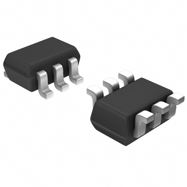
The BFS17SE6327HTSA1 is a dual NPN RF transistor manufactured by Infineon Technologies, designed for RF applications operating at 1.4GHz with a maximum collector-emitter breakdown voltage of 15V and power dissipation of 280mW. This component is classified as obsolete, necessitating identification of active substitute parts that maintain functional compatibility within specified electrical and mechanical parameters. The part is supplied in a 6-VSSOP (SOT-363) surface mount package with unlimited moisture sensitivity rating.
Substiute Parts
Key Parameters
| Parameter | Value | Unit |
|---|---|---|
| Manufacturer Part Number | BFS17SE6327HTSA1 | — |
| Manufacturer | Infineon Technologies | — |
| Transistor Type | 2 NPN (Dual) | — |
| Voltage - Collector Emitter Breakdown (Max) | 15V | V |
| Frequency - Transition | 1.4GHz | GHz |
| Noise Figure (Typ @ f) | 3dB ~ 5dB @ 800MHz | dB |
| Power - Max | 280mW | mW |
| DC Current Gain (hFE) (Min) | 40 @ 2mA, 1V | — |
| Current - Collector (Ic) (Max) | 25mA | mA |
| Operating Temperature (TJ) | 150°C | °C |
| Mounting Type | Surface Mount | — |
| Package / Case | 6-VSSOP, SC-88, SOT-363 | — |
| Product Status | Obsolete | — |
Substitute Part Grouping Explanation
Substitution of the BFS17SE6327HTSA1 is determined by the following critical electrical and mechanical parameters:
Primary Substitution Criteria:
- Transistor configuration: Single NPN or dual NPN topology
- Voltage rating: Collector-emitter breakdown voltage must equal or exceed 15V
- Frequency capability: Transition frequency must support 1.4GHz operation
- Power dissipation: Maximum power rating must accommodate 280mW or greater
- Current handling: Collector current rating must support 25mA maximum
- Operating temperature: Junction temperature rating of 150°C or higher
- Mounting: Surface mount technology with compatible package footprint
- Product status: Active or available inventory status preferred for long-term supply
Identified Substitute Parts:
- 2SC2714-O(TE85L,F) — Toshiba Semiconductor and Storage (Single NPN, Active Status)
- 2SC4726TLP — Rohm Semiconductor (Single NPN, Active Status)
Both substitutes are single NPN transistors with active product status, providing superior availability compared to the obsolete BFS17SE6327HTSA1. Electrical parameters of each substitute must be evaluated against application-specific requirements.
Parameter Comparison
| Parameter | BFS17SE6327HTSA1 (Main) | 2SC2714-O(TE85L,F) | 2SC4726TLP | Unit |
|---|---|---|---|---|
| Manufacturer | Infineon Technologies | Toshiba Semiconductor and Storage | Rohm Semiconductor | — |
| Transistor Type | 2 NPN (Dual) | NPN | NPN | — |
| Voltage - Collector Emitter Breakdown (Max) | 15V | 30V | 11V | V |
| Frequency - Transition | 1.4GHz | 550MHz | 3.2GHz | GHz |
| Noise Figure (Typ @ f) | 3dB ~ 5dB @ 800MHz | 2.5dB @ 100MHz | 3.5dB @ 500MHz | dB |
| Power - Max | 280mW | 100mW | 150mW | mW |
| DC Current Gain (hFE) (Min) | 40 @ 2mA, 1V | 70 @ 1mA, 6V | 56 @ 5mA, 10V | — |
| Current - Collector (Ic) (Max) | 25mA | 20mA | 50mA | mA |
| Operating Temperature (TJ) | 150°C | 125°C | 150°C | °C |
| Mounting Type | Surface Mount | Surface Mount | Surface Mount | — |
| Package / Case | 6-VSSOP, SC-88, SOT-363 | TO-236-3, SC-59, SOT-23-3 | SC-75, SOT-416 | — |
| Product Status | Obsolete | Active | Active | — |
| RoHS Status | — | RoHS Compliant | ROHS3 Compliant | — |
| Moisture Sensitivity Level (MSL) | 1 (Unlimited) | 1 (Unlimited) | 1 (Unlimited) | — |
Engineering Selection Recommendations
2SC2714-O(TE85L,F) — Toshiba Semiconductor and Storage
This substitute provides active product status with RoHS compliance certification. The 30V collector-emitter breakdown voltage exceeds the 15V requirement of the main part, offering enhanced voltage margin. However, the transition frequency of 550MHz is significantly lower than the 1.4GHz specification of the BFS17SE6327HTSA1, and maximum power dissipation of 100mW is substantially reduced from 280mW. The maximum collector current of 20mA approaches but does not exceed the 25mA requirement. Package footprint differs (SOT-23-3 versus SOT-363), requiring PCB layout modification. Operating temperature maximum of 125°C is 25°C lower than the main part specification.
2SC4726TLP — Rohm Semiconductor
This substitute provides active product status with ROHS3 compliance certification. The transition frequency of 3.2GHz exceeds the 1.4GHz requirement, supporting higher-frequency applications. Maximum collector current of 50mA substantially exceeds the 25mA specification. Operating temperature rating of 150°C matches the main part. However, the collector-emitter breakdown voltage of 11V falls below the 15V requirement, reducing voltage margin. Maximum power dissipation of 150mW is lower than the 280mW specification. Package footprint differs (SOT-416 versus SOT-363), requiring PCB layout modification.
Both substitutes are single NPN transistors, whereas the main part is a dual NPN configuration. Application circuit topology must accommodate this structural difference.
Frequently Asked Questions (FAQ)
Q: Why is the BFS17SE6327HTSA1 classified as obsolete?
A: The BFS17SE6327HTSA1 is designated as obsolete by Infineon Technologies, indicating discontinued manufacturing and limited long-term availability. Substitute parts with active product status are recommended for new designs and ongoing production requirements.
Q: Can the 2SC2714-O(TE85L,F) directly replace the BFS17SE6327HTSA1 in all applications?
A: Direct replacement is not universally applicable. The 2SC2714-O(TE85L,F) operates at 550MHz transition frequency, which is insufficient for applications requiring 1.4GHz performance. Additionally, the 100mW maximum power dissipation is lower than the 280mW specification. Package footprint differs, requiring PCB redesign. Voltage rating of 30V provides margin above the 15V requirement.
Q: Can the 2SC4726TLP directly replace the BFS17SE6327HTSA1 in all applications?
A: Direct replacement is not universally applicable. The 2SC4726TLP operates at 3.2GHz transition frequency, exceeding the 1.4GHz requirement and supporting higher-frequency applications. However, the 11V collector-emitter breakdown voltage is below the 15V specification, reducing voltage margin. Maximum power dissipation of 150mW is lower than the 280mW requirement. Package footprint differs, requiring PCB redesign.
Q: What is the significance of the dual NPN configuration in the BFS17SE6327HTSA1?
A: The BFS17SE6327HTSA1 contains two independent NPN transistors within a single 6-VSSOP package. Both substitute parts are single NPN transistors. Applications utilizing both transistors within the main part require either two substitute devices or alternative dual-transistor components to maintain functional equivalence.
Q: How do package differences affect substitution?
A: The BFS17SE6327HTSA1 uses a 6-VSSOP (SOT-363) package. The 2SC2714-O(TE85L,F) uses SOT-23-3 (TO-236-3), and the 2SC4726TLP uses SOT-416 (SC-75). Different package footprints require PCB layout modification, including trace routing, via placement, and thermal management considerations. Pin assignments must be verified against application schematics.
Q: What compliance certifications are relevant for substitute selection?
A: The 2SC2714-O(TE85L,F) carries RoHS Compliant certification. The 2SC4726TLP carries ROHS3 Compliant certification. Both parts maintain MSL 1 (Unlimited) moisture sensitivity rating, matching the main part. REACH compliance status should be verified for specific regulatory jurisdictions.
Q: Are there frequency-dependent application considerations?
A: Yes. The 2SC2714-O(TE85L,F) at 550MHz transition frequency is suitable for lower-frequency RF applications but insufficient for 1.4GHz operation. The 2SC4726TLP at 3.2GHz transition frequency supports higher-frequency applications beyond the 1.4GHz specification. Application frequency requirements determine which substitute is appropriate.
Q: What is the impact of reduced power dissipation in substitute parts?
A: Both substitutes have lower maximum power dissipation than the main part (100mW and 150mW versus 280mW). Applications requiring sustained power dissipation near 280mW may exceed the thermal limits of substitute parts. Thermal management design, including PCB copper area and heat sinking, must be re-evaluated for each substitute.
Alternative Parts

SJ6012L2TP
Littelfuse Inc.
6 Alternative Parts

JMK107BBJ476MA-RE
Taiyo Yuden
10 Alternative Parts

GMK107BBJ475MA-T
Taiyo Yuden
5 Alternative Parts
SJ6020N2ARP
Littelfuse Inc.
3 Alternative Parts
SJ6025R2ATP
Littelfuse Inc.
4 Alternative Parts

2474-05L
API Delevan Inc.
1 Alternative Parts

4590R-684K
API Delevan Inc.
1 Alternative Parts

CM6560R-334
API Delevan Inc.
1 Alternative Parts

CM6460-104
API Delevan Inc.
1 Alternative Parts

5526-12
API Delevan Inc.
1 Alternative Parts