


Request Quote
(Ships tomorrow)
BCR 148L3 E6327 Equivalent & Substitute Parts
Part Overview
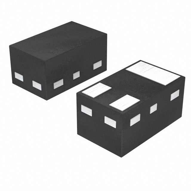
The BCR 148L3 E6327 is a pre-biased NPN bipolar junction transistor (BJT) manufactured by Infineon Technologies, designed for surface mount applications in the SC-101/SOT-883 package. This component integrates internal base and emitter resistors, enabling simplified circuit design for switching and amplification applications. The part is rated for 50 V collector-emitter breakdown voltage and 70 mA maximum collector current with 250 mW power dissipation.
The BCR 148L3 E6327 is currently discontinued at DiGi Electronics. Equivalent substitute parts are available from active manufacturers including Diodes Incorporated, Nexperia USA Inc., and NXP Semiconductors, offering comparable or enhanced electrical performance while maintaining functional compatibility.
Substiute Parts
Key Parameters
| Parameter | BCR 148L3 E6327 | Unit |
|---|---|---|
| Transistor Type | NPN - Pre-Biased | — |
| Voltage - Collector Emitter Breakdown (Max) | 50 | V |
| Current - Collector (Ic) (Max) | 70 | mA |
| Resistor - Base (R1) | 47 | kOhms |
| Resistor - Emitter Base (R2) | 47 | kOhms |
| DC Current Gain (hFE) (Min) @ Ic, Vce | 70 @ 5mA, 5V | — |
| Vce Saturation (Max) @ Ib, Ic | 300 | mV @ 500µA, 10mA |
| Frequency - Transition | 100 | MHz |
| Power - Max | 250 | mW |
| Package / Case | SC-101, SOT-883 | — |
| Mounting Type | Surface Mount | — |
| RoHS Status | ROHS3 Compliant | — |
| Product Status | Discontinued | — |
Substitute Part Grouping Explanation
Substitution eligibility for the BCR 148L3 E6327 is determined by the following critical parameters:
Mandatory Matching Criteria:
- Transistor Type: NPN - Pre-Biased
- Voltage - Collector Emitter Breakdown (Max): 50 V minimum
- Resistor - Base (R1): 47 kOhms
- Resistor - Emitter Base (R2): 47 kOhms (primary group) or alternative values (secondary group)
- Power - Max: 250 mW minimum
- Mounting Type: Surface Mount
- RoHS Status: ROHS3 Compliant
Performance Enhancement Allowances:
- Current - Collector (Ic) (Max): 70 mA or higher
- Frequency - Transition: 100 MHz or higher
- DC Current Gain (hFE): Comparable or higher
- Vce Saturation: Equal or lower values acceptable
Substitute parts are grouped into two categories based on internal resistor configuration:
Group 1 (R1=47kΩ, R2=47kΩ): DDTC144ELP-7, PDTC144EMB,315, PDTC144WM,315
Group 2 (R1=47kΩ, R2≠47kΩ): PDTC144VMB,315 (R2=10kΩ)
All substitute parts maintain the 50 V breakdown voltage, 250 mW power rating, and surface mount configuration. Substitute parts from Group 1 provide direct functional equivalence. Group 2 parts offer alternative biasing characteristics and require circuit evaluation.
Parameter Comparison
| Parameter | BCR 148L3 E6327 | DDTC144ELP-7 | PDTC144EMB,315 | PDTC144VMB,315 | PDTC144WM,315 | Unit |
|---|---|---|---|---|---|---|
| Manufacturer | Infineon Technologies | Diodes Incorporated | Nexperia USA Inc. | Nexperia USA Inc. | NXP Semiconductors | — |
| Transistor Type | NPN - Pre-Biased | NPN - Pre-Biased | NPN - Pre-Biased | NPN - Pre-Biased | NPN - Pre-Biased | — |
| Voltage - Collector Emitter Breakdown (Max) | 50 | 50 | 50 | 50 | 50 | V |
| Current - Collector (Ic) (Max) | 70 | 100 | 100 | 100 | 100 | mA |
| Resistor - Base (R1) | 47 | 47 | 47 | 47 | 47 | kOhms |
| Resistor - Emitter Base (R2) | 47 | 47 | 47 | 10 | 22 | kOhms |
| DC Current Gain (hFE) (Min) @ Ic, Vce | 70 @ 5mA, 5V | 68 @ 5mA, 5V | 80 @ 5mA, 5V | 40 @ 5mA, 5V | 60 @ 5mA, 5V | — |
| Vce Saturation (Max) @ Ib, Ic | 300 | 300 | 150 | 150 | 150 | mV @ 500µA, 10mA |
| Current - Collector Cutoff (Max) | 100 | 500 | 1000 | 1000 | 1000 | nA |
| Frequency - Transition | 100 | 250 | 230 | 230 | Not specified | MHz |
| Power - Max | 250 | 250 | 250 | 250 | 250 | mW |
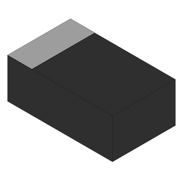
| Package / Case | SC-101, SOT-883 | 3-UFDFN | 3-XFDFN | 3-XFDFN | SC-101, SOT-883 | — |
| Mounting Type | Surface Mount | Surface Mount | Surface Mount | Surface Mount | Surface Mount | — |
| RoHS Status | ROHS3 Compliant | ROHS3 Compliant | ROHS3 Compliant | ROHS3 Compliant | Not specified | — |
| Product Status | Discontinued | Active | Active | Active | Active | — |
| Automotive Grade | Not specified | Not specified | AEC-Q100 | AEC-Q100 | Not specified | — |
Engineering Selection Recommendations
Primary Substitute (Direct Equivalence):
PDTC144WM,315 from NXP Semiconductors is the recommended primary substitute. This part maintains identical package configuration (SC-101, SOT-883) to the BCR 148L3 E6327, eliminating PCB layout modifications. The part is in active production status with high inventory availability (121,126 pcs). Electrical parameters meet or exceed the original specification: 100 mA collector current (vs. 70 mA), 250 mW power rating, 50 V breakdown voltage, and 47 kOhm base and 22 kOhm emitter-base resistors. The lower Vce saturation (150 mV vs. 300 mV) provides improved switching performance.
Secondary Substitutes (Package Modification Required):
PDTC144EMB,315 and DDTC144ELP-7 are functionally equivalent alternatives with enhanced specifications. Both parts feature identical internal resistor configuration (R1=47kΩ, R2=47kΩ) and improved Vce saturation characteristics (150 mV). PDTC144EMB,315 includes AEC-Q100 automotive qualification and is available in high volume (10,025 pcs). DDTC144ELP-7 offers the highest transition frequency (250 MHz) and is supplied in tape & reel packaging. Both require package footprint conversion from SC-101/SOT-883 to 3-DFN variants.
Alternative Substitute (Modified Biasing):
PDTC144VMB,315 provides an alternative with modified emitter-base resistor (R2=10kΩ vs. 47kΩ). This configuration produces lower DC current gain (40 vs. 70) and altered biasing characteristics. Selection of this part requires circuit-level evaluation to confirm compatibility with intended application biasing requirements. AEC-Q100 qualification is available.
Compliance Considerations:
All recommended substitutes maintain ROHS3 compliance and EAR99 export classification. PDTC144EMB,315 and PDTC144VMB,315 include AEC-Q100 automotive qualification for applications requiring automotive-grade components.
Frequently Asked Questions (FAQ)
Q1: Can PDTC144WM,315 be used as a direct drop-in replacement for BCR 148L3 E6327?
A: Yes. PDTC144WM,315 maintains the same package configuration (SC-101, SOT-883) and internal resistor values (R1=47kΩ, R2=22kΩ). No PCB modifications are required. The 22 kOhm emitter-base resistor differs from the original 47 kOhm value, resulting in higher DC current gain (60 vs. 70 @ 5mA, 5V). Circuit performance remains compatible for standard switching applications.
Q2: What is the difference between Group 1 and Group 2 substitute parts?
A: Group 1 parts (DDTC144ELP-7, PDTC144EMB,315, PDTC144WM,315) maintain the 47 kOhm base resistor (R1) with varying emitter-base resistor (R2) values. Group 2 part (PDTC144VMB,315) features a 10 kOhm emitter-base resistor, producing significantly lower DC current gain (40 vs. 70). Group 1 parts provide closer functional equivalence. Group 2 selection requires application-specific evaluation.
Q3: Why do substitute parts show higher collector current ratings (100 mA vs. 70 mA)?
A: Substitute parts are designed with enhanced current handling capability while maintaining the same 50 V breakdown voltage and 250 mW power dissipation limits. The higher Ic(Max) rating reflects improved die design and does not affect compatibility. Operating current in the application remains limited by circuit design, not the component rating.
Q4: Are package changes required when substituting with DDTC144ELP-7 or PDTC144EMB,315?
A: Yes. Both parts use 3-DFN packages (X1-DFN1006-3 and DFN1006B-3 respectively) instead of the original SC-101/SOT-883 package. PCB footprint modification is required. PDTC144WM,315 eliminates this requirement by maintaining the SC-101/SOT-883 package.
Q5: What does the lower Vce saturation (150 mV vs. 300 mV) in substitute parts mean for circuit operation?
A: Lower Vce saturation indicates improved switching efficiency and reduced power dissipation during saturation. This enhancement is beneficial for switching applications and does not negatively impact circuit compatibility. The original 300 mV specification is not a requirement for substitution; lower values represent performance improvement.
Q6: Are automotive-qualified versions available?
A: Yes. PDTC144EMB,315 and PDTC144VMB,315 include AEC-Q100 automotive qualification. These parts are suitable for automotive applications requiring qualified component status. PDTC144WM,315 and DDTC144ELP-7 do not specify automotive qualification.
Q7: What inventory status should be considered for production planning?
A: PDTC144WM,315 offers the highest inventory availability (121,126 pcs), ensuring supply continuity. PDTC144EMB,315 and PDTC144VMB,315 provide substantial inventory (10,025 and 10,934 pcs respectively). DDTC144ELP-7 is available with 1,469 pcs. All parts are in active production status.
Q8: Can the BCR 148L3 E6327 be used interchangeably with these substitutes in existing designs?
A: PDTC144WM,315 provides direct interchangeability without design modification. DDTC144ELP-7 and PDTC144EMB,315 require PCB footprint redesign due to package differences. PDTC144VMB,315 requires circuit evaluation due to modified biasing characteristics (R2=10kΩ). All parts maintain the 50 V/250 mW power envelope and NPN pre-biased configuration.
Alternative Parts

SJ6012L2TP
Littelfuse Inc.
6 Alternative Parts

JMK107BBJ476MA-RE
Taiyo Yuden
10 Alternative Parts

GMK107BBJ475MA-T
Taiyo Yuden
5 Alternative Parts
SJ6020N2ARP
Littelfuse Inc.
3 Alternative Parts
SJ6025R2ATP
Littelfuse Inc.
4 Alternative Parts

2474-05L
API Delevan Inc.
1 Alternative Parts

4590R-684K
API Delevan Inc.
1 Alternative Parts

CM6560R-334
API Delevan Inc.
1 Alternative Parts

CM6460-104
API Delevan Inc.
1 Alternative Parts

5526-12
API Delevan Inc.
1 Alternative Parts