


Request Quote
(Ships tomorrow)
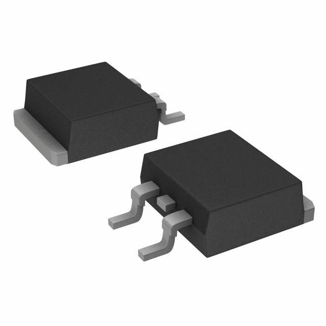
AUIRFS3006-7P N-Channel 60V 240A MOSFET Equivalent & Substitute Parts
Part Overview
The AUIRFS3006-7P is an N-Channel MOSFET manufactured by Infineon Technologies, rated for 60V drain-to-source voltage and 240A continuous drain current in a D2PAK surface mount package. This device is part of the HEXFET® series and is classified as obsolete. Due to its obsolete status, equivalent and substitute parts from active product lines are necessary for new designs and ongoing production requirements. Substitute devices maintain the same voltage rating and package form factor while offering comparable electrical performance characteristics.
Substiute Parts
Key Parameters
| Parameter | Value | Unit |
|---|---|---|
| Drain to Source Voltage (Vdss) | 60 | V |
| Continuous Drain Current (Id) @ 25°C | 240 | A |
| On-State Resistance (Rds On Max) @ Id, Vgs | 2.1 mOhm @ 168A, 10V | mOhm |
| Gate Threshold Voltage (Vgs(th) Max) @ Id | 4 | V @ 250µA |
| Gate Charge (Qg Max) @ Vgs | 300 | nC @ 10V |
| Maximum Gate Voltage (Vgs Max) | ±20 | V |
| Input Capacitance (Ciss Max) @ Vds | 8850 | pF @ 50V |
| Power Dissipation (Max) | 375 | W |
| Operating Temperature Range | -55 to 175 | °C |
| Package Type | TO-263-7, D2PAK (6 Leads + Tab) | — |
| Mounting Type | Surface Mount | — |
| Product Status | Obsolete | — |
Substitute Part Grouping Explanation
Substitute parts for the AUIRFS3006-7P are selected based on the following critical parameters that determine functional equivalence:
Primary Selection Criteria:
- Drain-to-Source Voltage (Vdss): 60V (exact match required)
- Package Type: D2PAK or TO-263 surface mount configuration
- Operating Temperature Range: -55°C to 175°C (minimum requirement)
- FET Type: N-Channel MOSFET technology
Secondary Compatibility Parameters:
- On-State Resistance (Rds On): Comparable performance at rated current
- Gate Charge (Qg): Switching characteristics for drive circuit compatibility
- Maximum Gate Voltage (Vgs Max): ±20V or greater for gate drive compatibility
- Continuous Drain Current (Id): Equal to or greater than 120A minimum
The substitute parts listed below maintain the 60V voltage rating and surface mount D2PAK package configuration. While continuous drain current ratings vary (180A, 120A), these devices are suitable for applications where the full 240A capability is not required or where thermal management allows operation at reduced current levels. All substitute parts are from active product lines with current manufacturing status and full RoHS3 compliance.
Parameter Comparison
| Parameter | AUIRFS3006-7P (Main) | IPB017N06N3GATMA1 | BUK962R5-60E,118 | SQM50020EL_GE3 | SUM50020EL-GE3 |
|---|---|---|---|---|---|
| Manufacturer | Infineon Technologies | Infineon Technologies | Nexperia USA Inc. | Vishay Siliconix | Vishay Siliconix |
| Vdss (V) | 60 | 60 | 60 | 60 | 60 |
| Id @ 25°C (A) | 240 | 180 | 120 | 120 | 120 |
| Rds On (Max) @ Id, Vgs (mOhm) | 2.1 @ 168A, 10V | 1.7 @ 100A, 10V | 2.5 @ 25A, 5V | 2.0 @ 30A, 10V | 2.1 @ 30A, 10V |
| Vgs(th) (Max) @ Id (V) | 4 @ 250µA | 4 @ 196µA | 2.1 @ 1mA | 2.5 @ 250µA | 2.5 @ 250µA |
| Qg (Max) @ Vgs (nC) | 300 @ 10V | 275 @ 10V | 120 @ 5V | 200 @ 10V | 126 @ 10V |
| Vgs (Max) (V) | ±20 | ±20 | ±10 | ±20 | ±20 |
| Ciss (Max) @ Vds (pF) | 8850 @ 50V | 23000 @ 30V | 17450 @ 25V | 15100 @ 25V | 11113 @ 30V |
| Power Dissipation (Max) (W) | 375 | 250 | 357 | 375 | 375 |
| Operating Temperature (°C) | -55 to 175 | -55 to 175 | -55 to 175 | -55 to 175 | -55 to 175 |
| Package | TO-263-7, D2PAK (6 Leads + Tab) | PG-TO263-7 | TO-263-3, D2PAK (2 Leads + Tab) | TO-263-3, D2PAK (2 Leads + Tab) | TO-263-3, D2PAK (2 Leads + Tab) |
| Product Status | Obsolete | Active | Active | Active | Active |
| Series | HEXFET® | OptiMOS™ | TrenchMOS™ | TrenchFET® | TrenchFET® |
| RoHS3 Compliant | Yes | Yes | Yes | Yes | Yes |
| MSL Rating | 1 (Unlimited) | 1 (Unlimited) | 1 (Unlimited) | 1 (Unlimited) | 1 (Unlimited) |
Engineering Selection Recommendations
IPB017N06N3GATMA1 (Infineon Technologies OptiMOS™)
This substitute is from the same manufacturer as the main part and represents the active-production equivalent within Infineon's current MOSFET portfolio. The IPB017N06N3GATMA1 maintains the 60V voltage rating and D2PAK package configuration. The continuous drain current rating of 180A is lower than the original 240A specification; however, this device is suitable for applications operating at or below 180A. The on-state resistance of 1.7 mOhm at 100A, 10V demonstrates improved performance characteristics compared to the main part. Gate charge of 275 nC at 10V is comparable to the original specification. This device carries active product status with full RoHS3 compliance and unlimited moisture sensitivity rating.
BUK962R5-60E,118 (Nexperia USA Inc. TrenchMOS™)
This substitute maintains the 60V voltage rating and D2PAK package form factor. The continuous drain current rating of 120A represents a significant reduction from the original 240A specification and is suitable only for applications with lower current requirements. The device features a lower gate charge of 120 nC at 5V, which may reduce gate drive power requirements. The maximum gate voltage rating of ±10V is lower than the original ±20V specification and must be verified for compatibility with existing gate drive circuits. This device includes automotive-grade qualification (AEC-Q101) and carries active product status with full RoHS3 compliance.
SQM50020EL_GE3 (Vishay Siliconix TrenchFET®)
This substitute maintains the 60V voltage rating and D2PAK package configuration. The continuous drain current rating of 120A is lower than the original 240A specification. The on-state resistance of 2.0 mOhm at 30A, 10V is comparable to the main part. Gate charge of 200 nC at 10V is lower than the original specification. The maximum gate voltage rating of ±20V matches the original specification. This device includes automotive-grade qualification (AEC-Q101) and carries active product status with full RoHS3 compliance and unlimited moisture sensitivity rating.
SUM50020EL-GE3 (Vishay Siliconix TrenchFET®)
This substitute maintains the 60V voltage rating and D2PAK package configuration. The continuous drain current rating of 120A is lower than the original 240A specification. The on-state resistance of 2.1 mOhm at 30A, 10V matches the original specification. Gate charge of 126 nC at 10V is significantly lower than the original specification, indicating improved switching characteristics. The maximum gate voltage rating of ±20V matches the original specification. This device carries active product status with full RoHS3 compliance and unlimited moisture sensitivity rating.
All substitute parts are RoHS3 compliant with MSL rating of 1 (unlimited moisture sensitivity). Selection among these substitutes depends on specific application requirements regarding continuous drain current, gate charge characteristics, and manufacturer preference.
Frequently Asked Questions (FAQ)
Q: Can the IPB017N06N3GATMA1 directly replace the AUIRFS3006-7P in all applications?
A: The IPB017N06N3GATMA1 is suitable for applications where the continuous drain current requirement does not exceed 180A. Both devices share the same 60V voltage rating, D2PAK package configuration, and operating temperature range. Gate charge and on-state resistance characteristics are comparable. Applications requiring the full 240A continuous drain current capability of the original part require evaluation of thermal management and current distribution across multiple devices or selection of a higher-current substitute.
Q: What is the difference between the D2PAK package variants listed in the parameter comparison?
A: The main part AUIRFS3006-7P uses a TO-263-7 D2PAK configuration with 6 leads plus tab. The substitute parts use TO-263-3 D2PAK configurations with 2 leads plus tab. Both package types are surface mount D2PAK variants with the same thermal tab interface. The primary difference is the number of internal leads; however, the electrical connection points (drain, gate, source) remain functionally equivalent. PCB layout compatibility must be verified for the specific package variant selected.
Q: Why does the BUK962R5-60E,118 have a lower maximum gate voltage rating of ±10V compared to the original ±20V?
A: The BUK962R5-60E,118 is specified with a maximum gate voltage of ±10V, which is a design characteristic of this particular device. Applications using gate drive circuits rated for ±20V operation must be evaluated to ensure compatibility with this lower rating. Gate drive circuits operating within the ±10V range are fully compatible with this substitute.
Q: Are all substitute parts suitable for automotive applications?
A: The BUK962R5-60E,118 and SQM50020EL_GE3 carry automotive-grade qualification (AEC-Q101). The IPB017N06N3GATMA1 and SUM50020EL-GE3 do not list automotive qualification in the provided specifications. Application requirements for automotive-grade components must be verified before selection.
Q: How do the gate charge specifications affect circuit design?
A: Gate charge (Qg) determines the amount of charge required to switch the MOSFET on or off and directly impacts gate drive circuit design. The main part specifies 300 nC at 10V. Substitute parts range from 120 nC to 275 nC at their respective gate voltages. Lower gate charge values reduce gate drive power dissipation and may allow faster switching speeds. Gate drive circuits must be designed or verified to supply the required charge for the selected device.
Q: What is the significance of the on-state resistance (Rds On) differences among substitute parts?
A: On-state resistance determines conduction losses when the MOSFET is in the on-state. Lower Rds On values result in reduced power dissipation and heat generation. The main part specifies 2.1 mOhm at 168A, 10V. Substitute parts range from 1.7 mOhm to 2.5 mOhm at their respective measurement conditions. Selection based on Rds On should consider the actual operating current and voltage conditions in the target application.
Q: Can multiple lower-current substitute devices be paralleled to achieve the original 240A capability?
A: Paralleling MOSFETs is a valid design approach; however, it requires careful circuit design to ensure balanced current distribution among devices. This approach is outside the scope of direct part substitution and requires detailed thermal and electrical analysis specific to the application circuit topology.
Q: What is the moisture sensitivity level (MSL) rating, and why is it important?
A: MSL rating indicates the maximum time a component can be exposed to ambient conditions before soldering without risk of moisture-induced failures. All listed parts carry MSL rating of 1 (unlimited), meaning they can be stored indefinitely at room temperature without moisture-related degradation concerns. This specification is identical across all parts listed.
Q: Are there any lead-free or RoHS compliance differences among the substitute parts?
A: All parts listed, including the main part AUIRFS3006-7P, are RoHS3 compliant. No differences in lead-free or RoHS compliance status exist among the parts presented. All parts meet the same environmental compliance standards.
Alternative Parts

SJ6012L2TP
Littelfuse Inc.
6 Alternative Parts

JMK107BBJ476MA-RE
Taiyo Yuden
10 Alternative Parts

GMK107BBJ475MA-T
Taiyo Yuden
5 Alternative Parts
SJ6020N2ARP
Littelfuse Inc.
3 Alternative Parts
SJ6025R2ATP
Littelfuse Inc.
4 Alternative Parts

2474-05L
API Delevan Inc.
1 Alternative Parts

4590R-684K
API Delevan Inc.
1 Alternative Parts

CM6560R-334
API Delevan Inc.
1 Alternative Parts

CM6460-104
API Delevan Inc.
1 Alternative Parts

5526-12
API Delevan Inc.
1 Alternative Parts