


Request Quote
(Ships tomorrow)
AUIRF2907Z N-Channel MOSFET Equivalent & Substitute Parts
Part Overview
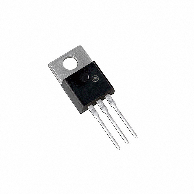
The AUIRF2907Z is an N-Channel MOSFET manufactured by Infineon Technologies, rated for 75V drain-to-source voltage and 75A continuous drain current in a TO-220AB through-hole package. This device is part of the HEXFET® series and is classified as obsolete. Due to its obsolete status, equivalent and substitute parts from active product lines or alternative manufacturers are necessary for new designs and ongoing production requirements. Substitute parts must maintain compatibility across electrical ratings, thermal characteristics, and mechanical packaging to ensure direct replacement capability.
Substiute Parts
Key Parameters
| Parameter | Value | Unit |
|---|---|---|
| FET Type | N-Channel | — |
| Drain to Source Voltage (Vdss) | 75 | V |
| Continuous Drain Current (Id) @ 25°C | 75 | A |
| Rds On (Max) @ Id, Vgs | 4.5 mOhm @ 75A, 10V | mOhm |
| Gate Charge (Qg) @ Vgs | 270 nC @ 10V | nC |
| Power Dissipation (Max) | 300 | W |
| Operating Temperature Range | -55 to 175 | °C |
| Mounting Type | Through Hole | — |
| Package / Case | TO-220-3 | — |
Substitute Part Grouping Explanation
Substitution of the AUIRF2907Z is determined by the following critical parameters:
Electrical Compatibility Criteria:
- Drain-to-Source Voltage (Vdss) must be equal to or greater than 75V
- Continuous Drain Current (Id) must be equal to or greater than 75A at 25°C
- Gate-Source Voltage (Vgs) maximum rating must be ±20V
- Operating temperature range must encompass -55°C to 175°C
- On-state resistance (Rds On) should be comparable to maintain thermal performance
Mechanical Compatibility Criteria:
- Mounting type must be Through Hole
- Package must be TO-220-3 or equivalent footprint
- Thermal characteristics (Power Dissipation) should support the application thermal budget
Substitute parts are grouped into two categories:
- Direct Electrical Equivalents – Parts with Vdss ≥ 75V and Id ≥ 75A, maintaining similar Rds On and thermal performance
- Functional Alternatives – Parts with higher voltage or current ratings that operate within the same package and thermal envelope, suitable for applications where the AUIRF2907Z is used
Parameter Comparison
| Parameter | AUIRF2907Z (Main) | IPP120N08S404AKSA1 | FDP038AN06A0-F102 | IXFP220N06T3 | STP140NF75 |
|---|---|---|---|---|---|
| Manufacturer | Infineon | Infineon | onsemi | IXYS | STMicroelectronics |
| Vdss (V) | 75 | 80 | 60 | 60 | 75 |
| Id @ 25°C (A) | 75 | 120 | 80 | 220 | 120 |
| Rds On (Max) @ Vgs 10V (mOhm) | 4.5 @ 75A | 4.4 @ 100A | 3.8 @ 80A | 4.0 @ 100A | 7.5 @ 70A |
| Gate Charge @ 10V (nC) | 270 | 95 | 124 | 136 | 218 |
| Power Dissipation (W) | 300 | 179 | 310 | 440 | 310 |
| Operating Temp Range (°C) | -55 to 175 | -55 to 175 | -55 to 175 | -55 to 175 | -55 to 175 |
| Package | TO-220-3 | TO-220-3 | TO-220-3 | TO-220-3 | TO-220-3 |
| Mounting Type | Through Hole | Through Hole | Through Hole | Through Hole | Through Hole |
| Product Status | Obsolete | Obsolete | Active | Last Time Buy | Active |
| RoHS Compliance | — | ROHS3 | ROHS3 | ROHS3 | ROHS3 |
Engineering Selection Recommendations
STP140NF75 (STMicroelectronics) – Primary Recommendation
The STP140NF75 is the closest electrical equivalent to the AUIRF2907Z. It maintains the same 75V Vdss rating, exceeds the 75A current requirement at 120A, and operates within the identical temperature range. The device is in active product status with ROHS3 compliance, ensuring long-term availability and regulatory compliance. The TO-220-3 package provides direct mechanical compatibility. Gate charge of 218 nC is comparable to the original 270 nC, indicating similar switching characteristics. This part is suitable for direct replacement in applications where the AUIRF2907Z was originally specified.
FDP038AN06A0-F102 (onsemi) – Alternative for Lower Voltage Applications
The FDP038AN06A0-F102 operates at 60V Vdss, which is lower than the original 75V specification. This part is suitable only for applications where the actual operating voltage does not exceed 60V. The device offers superior Rds On performance at 3.8 mOhm and higher power dissipation capability at 310W. Active product status and ROHS3 compliance support long-term availability. Use this part only when voltage derating is acceptable for the application.
IPP120N08S404AKSA1 (Infineon) – Higher Voltage Alternative
The IPP120N08S404AKSA1 provides 80V Vdss and 120A current rating, exceeding the original specifications. This part is classified as obsolete but remains available in inventory. The OptiMOS™ series technology offers lower gate charge at 95 nC, which may reduce switching losses. Automotive qualification (AEC-Q101) provides additional reliability assurance. This part is suitable for applications requiring higher voltage margin or where Infineon OptiMOS™ technology is preferred.
IXFP220N06T3 (IXYS) – High Current Alternative
The IXFP220N06T3 operates at 60V Vdss with exceptional 220A current rating and 440W power dissipation. This part is classified as Last Time Buy, indicating limited future availability. The HiperFET™ and TrenchT3™ technology provides superior current handling. Use this part only when higher current capacity is required and voltage derating to 60V is acceptable. Not recommended for new designs due to Last Time Buy status.
Frequently Asked Questions (FAQ)
Q: Can the STP140NF75 directly replace the AUIRF2907Z without circuit modifications?
A: Yes. The STP140NF75 maintains the same 75V Vdss rating, exceeds the 75A current requirement, and uses the identical TO-220-3 package. Operating temperature range, gate-source voltage limits, and thermal characteristics are compatible. No circuit modifications are required.
Q: Why is the FDP038AN06A0-F102 listed as a substitute if its Vdss is only 60V?
A: The FDP038AN06A0-F102 is a functional alternative for applications where the actual operating voltage does not exceed 60V. It provides superior on-state resistance and power dissipation capability. Substitution is valid only when the application voltage margin permits 60V operation.
Q: What is the significance of the "Last Time Buy" status for the IXFP220N06T3?
A: Last Time Buy status indicates that the manufacturer has announced end-of-life for this product. Existing inventory may be available, but future procurement will not be possible. This part should not be selected for new designs requiring long-term component availability.
Q: Are all substitute parts RoHS3 compliant?
A: The FDP038AN06A0-F102, IXFP220N06T3, and STP140NF75 are all ROHS3 compliant. The IPP120N08S404AKSA1 does not specify RoHS status in the provided data. Verify RoHS compliance requirements with your procurement specifications before final selection.
Q: How do gate charge differences affect circuit performance?
A: Gate charge (Qg) determines the energy required to switch the MOSFET. The AUIRF2907Z has 270 nC gate charge. The STP140NF75 has 218 nC, the FDP038AN06A0-F102 has 124 nC, and the IPP120N08S404AKSA1 has 95 nC. Lower gate charge reduces driver power dissipation and may improve switching speed. Verify that your gate driver can supply the required gate current for the selected substitute.
Q: Can I use a substitute with higher current rating in place of the AUIRF2907Z?
A: Yes, provided all other electrical parameters are compatible. Higher current rating does not negatively affect circuit operation. Verify that Vdss, Vgs limits, operating temperature range, and package compatibility are maintained. Higher current rating may provide additional design margin.
Q: What is the impact of different Rds On values on thermal performance?
A: On-state resistance (Rds On) directly affects power dissipation during conduction. Lower Rds On reduces I²R losses and heat generation. The AUIRF2907Z has 4.5 mOhm Rds On. The FDP038AN06A0-F102 offers 3.8 mOhm (lower losses), while the STP140NF75 has 7.5 mOhm (higher losses). Verify that thermal management design accommodates the selected part's power dissipation characteristics.
Q: Is the TO-220-3 package identical across all substitute parts?
A: All substitute parts use TO-220-3 package designation, which provides mechanical and thermal compatibility. However, verify PCB footprint and heatsink mounting interface with the specific manufacturer datasheet to ensure proper thermal coupling and mechanical fit.
Alternative Parts

SJ6012L2TP
Littelfuse Inc.
6 Alternative Parts

JMK107BBJ476MA-RE
Taiyo Yuden
10 Alternative Parts

GMK107BBJ475MA-T
Taiyo Yuden
5 Alternative Parts
SJ6020N2ARP
Littelfuse Inc.
3 Alternative Parts
SJ6025R2ATP
Littelfuse Inc.
4 Alternative Parts

2474-05L
API Delevan Inc.
1 Alternative Parts

4590R-684K
API Delevan Inc.
1 Alternative Parts

CM6560R-334
API Delevan Inc.
1 Alternative Parts

CM6460-104
API Delevan Inc.
1 Alternative Parts

5526-12
API Delevan Inc.
1 Alternative Parts