


Request Quote
(Ships tomorrow)
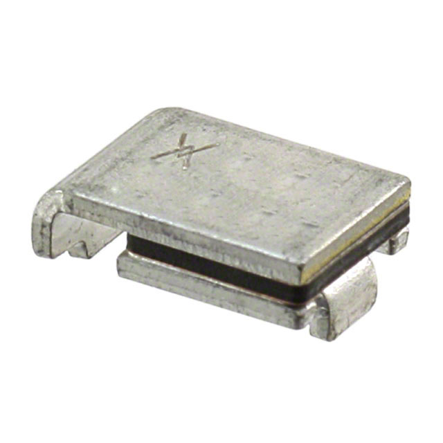
ASMD125F-2 Polymeric PTC Resettable Fuse Equivalent & Substitute Parts
Part Overview
The ASMD125F-2 is a polymeric PTC resettable fuse manufactured by Littelfuse Inc. in the PolySwitch® series. This surface mount 2-SMD component provides overcurrent protection with a maximum voltage rating of 16V and a hold current of 1.04A. The part is actively produced and widely used in electronic circuits requiring automatic reset protection without component replacement. Substitute parts are identified when equivalent electrical and mechanical specifications align with application requirements and packaging constraints.
Substiute Parts
Key Parameters
| Parameter | Value |
|---|---|
| Manufacturer | Littelfuse Inc. |
| Part Number | ASMD125F-2 |
| Series | PolySwitch®, ASMD |
| Type | Polymeric PTC Resettable Fuse |
| Voltage - Max | 16V |
| Current - Hold (Ih) | 1.04A |
| Current - Trip (It) | 2.46A |
| Mounting Type | Surface Mount |
| Package / Case | 2-SMD |
| Size / Dimension | 0.290" L x 0.202" W (7.36mm x 5.12mm) |
| Thickness (Max) | 0.118" (3.00mm) |
| Operating Temperature | -40°C ~ 85°C |
| RoHS Status | ROHS3 Compliant |
| Product Status | Active |
Substitute Part Grouping Explanation
Substitution eligibility for the ASMD125F-2 is determined by the following critical parameters:
Electrical Compatibility:
- Voltage rating must be equal to or greater than 16V
- Hold current (Ih) must be within the application tolerance of 1.04A
- Trip current (It) must provide equivalent protection response
- Resistance characteristics (initial and post-trip) must support circuit performance
Mechanical Compatibility:
- Package type must be 2-SMD surface mount
- Physical dimensions must fit within PCB layout constraints (7.36mm x 5.12mm maximum)
- Thickness must not exceed 3.00mm for board assembly compatibility
Regulatory & Environmental:
- RoHS3 compliance required
- Operating temperature range must cover -40°C to 85°C
- AEC-Q200 automotive qualification preferred for reliability
The identified substitute MF-SM125-2 meets these criteria with minor parameter variations within acceptable engineering tolerances.
Parameter Comparison
| Parameter | ASMD125F-2 (Littelfuse) | MF-SM125-2 (Bourns) | Compatibility Notes |
|---|---|---|---|
| Voltage - Max | 16V | 15V | Main part rated higher; substitute acceptable for ≤15V applications |
| Current - Hold (Ih) (Max) | 1.04A | 1.25A | Substitute has higher hold current; verify circuit tolerance |
| Current - Trip (It) | 2.46A | 2.5A | Functionally equivalent trip thresholds |
| Current - Max | 40A | 100A | Substitute rated for higher maximum current |
| Time to Trip | 20s | 2s | Substitute trips significantly faster; verify application requirements |
| Resistance - Initial (Ri) (Min) | 57mOhms | 70mOhms | Minimal difference; both acceptable for most applications |
| Resistance - Post Trip (R1) (Max) | 250mOhms | 250mOhms | Identical post-trip resistance |
| Operating Temperature | -40°C ~ 85°C | -40°C ~ 85°C | Identical operating range |
| Mounting Type | Surface Mount | Surface Mount | Compatible |
| Package / Case | 2-SMD | 2-SMD | Compatible |
| Size / Dimension | 0.290" L x 0.202" W (7.36mm x 5.12mm) | 0.287" L x 0.214" W (7.31mm x 5.44mm) | Dimensions within 0.1mm tolerance; footprint compatible |
| Thickness (Max) | 0.118" (3.00mm) | 0.118" (3.00mm) | Identical thickness |
| RoHS Status | ROHS3 Compliant | ROHS3 Compliant | Both compliant |
| Ratings | AEC-Q200 | AEC-Q200 | Both automotive qualified |
| Product Status | Active | Active | Both actively manufactured |
Engineering Selection Recommendations
Primary Part (ASMD125F-2): Use when 16V maximum voltage rating is required or when the 20-second trip time is specified for the application. AEC-Q200 certification and active production status ensure supply continuity and reliability for automotive and industrial applications.
Substitute Part (MF-SM125-2): Use when supply constraints require alternative sourcing. The substitute is suitable for applications operating at 15V or below. The faster 2-second trip time may be advantageous for applications requiring rapid fault response. Both parts carry AEC-Q200 certification and ROHS3 compliance. Verify that the higher hold current (1.25A vs. 1.04A) and faster trip response align with circuit protection requirements before implementation.
Substitution Constraints:
- Do not use MF-SM125-2 in circuits requiring 16V operation
- Confirm circuit tolerance for the 0.21A increase in hold current
- Verify that 2-second trip time does not cause nuisance tripping in the target application
- Both parts are surface mount 2-SMD with compatible footprints and identical thickness
Frequently Asked Questions (FAQ)
Q: Can MF-SM125-2 replace ASMD125F-2 in all applications?
A: No. The MF-SM125-2 has a maximum voltage rating of 15V compared to 16V for the ASMD125F-2. Use the substitute only in circuits operating at 15V or below. Additionally, the faster trip time (2 seconds vs. 20 seconds) must be verified as acceptable for the specific application to prevent nuisance tripping.
Q: What is the difference in hold current between these parts?
A: The ASMD125F-2 has a maximum hold current of 1.04A, while the MF-SM125-2 is rated at 1.25A. This 0.21A difference means the substitute will tolerate higher continuous current before tripping. Verify that your circuit design accommodates this higher threshold.
Q: Are the physical dimensions compatible?
A: Yes. Both parts are 2-SMD surface mount packages with identical thickness (3.00mm). The length and width differ by less than 0.1mm (ASMD125F-2: 7.36mm x 5.12mm; MF-SM125-2: 7.31mm x 5.44mm), making them footprint-compatible on standard PCB layouts.
Q: Do both parts meet automotive standards?
A: Yes. Both the ASMD125F-2 and MF-SM125-2 carry AEC-Q200 certification, indicating qualification for automotive applications. Both are ROHS3 compliant and actively produced.
Q: What does "time to trip" mean, and why does it differ?
A: Time to trip is the duration required for the fuse to transition from normal operation to the tripped (high-resistance) state when overcurrent is detected. The ASMD125F-2 requires 20 seconds, while the MF-SM125-2 requires 2 seconds. The faster response of the substitute may provide better protection in some applications but could cause false trips if the circuit experiences brief current surges during normal operation.
Q: Can I use these parts interchangeably in existing designs?
A: Substitution requires verification of three factors: (1) the circuit operates at 15V or below, (2) the higher hold current (1.25A) is acceptable, and (3) the faster trip time does not cause nuisance tripping. If all three conditions are met, the parts are mechanically and electrically compatible for PCB assembly.
Alternative Parts

SJ6012L2TP
Littelfuse Inc.
6 Alternative Parts

JMK107BBJ476MA-RE
Taiyo Yuden
10 Alternative Parts

GMK107BBJ475MA-T
Taiyo Yuden
5 Alternative Parts
SJ6020N2ARP
Littelfuse Inc.
3 Alternative Parts
SJ6025R2ATP
Littelfuse Inc.
4 Alternative Parts

2474-05L
API Delevan Inc.
1 Alternative Parts

4590R-684K
API Delevan Inc.
1 Alternative Parts

CM6560R-334
API Delevan Inc.
1 Alternative Parts

CM6460-104
API Delevan Inc.
1 Alternative Parts

5526-12
API Delevan Inc.
1 Alternative Parts