


Request Quote
(Ships tomorrow)
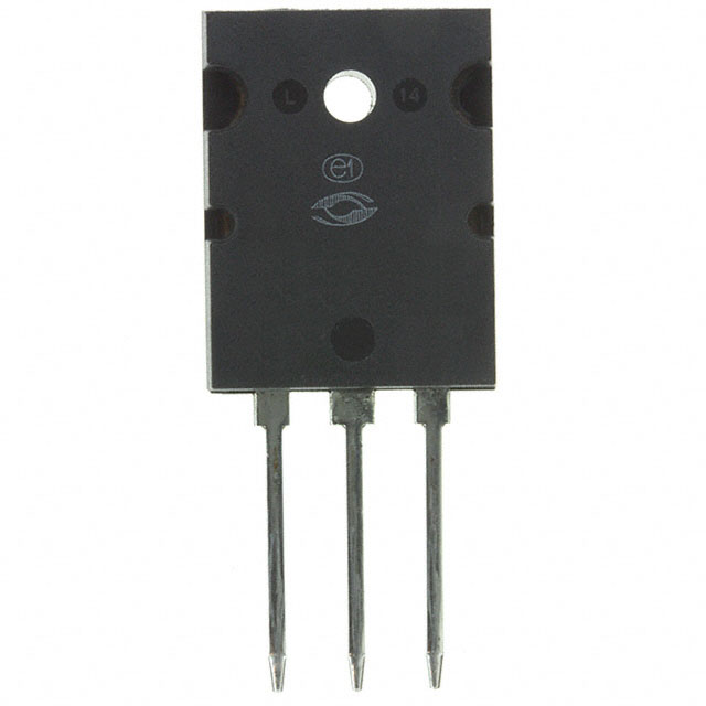
APT60M80L2VRG N-Channel 600V 65A Power MOSFET Equivalent & Substitute Parts
Part Overview
The APT60M80L2VRG is an N-Channel 600V power MOSFET manufactured by Microchip Technology, designed for high-current switching applications in the 600V class. This device features a maximum continuous drain current of 65A at 25°C case temperature, with a maximum on-resistance of 80mOhm at rated conditions. The part is packaged in the TO-264-3 (264 MAX™ [L2]) through-hole format and is currently in active production status.
Substitute parts are necessary when the APT60M80L2VRG reaches end-of-life, experiences supply constraints, or when design requirements necessitate alternative electrical or thermal characteristics within the 600V N-Channel MOSFET category.
Substiute Parts
Key Parameters
| Parameter | Value | Unit |
|---|---|---|
| Drain to Source Voltage (Vdss) | 600 | V |
| Continuous Drain Current (Id) @ 25°C | 65 | A |
| On-Resistance (Rds On Max) @ 32.5A, 10V | 80 | mOhm |
| Gate Threshold Voltage (Vgs(th) Max) @ 5mA | 4 | V |
| Gate Charge (Qg Max) @ 10V | 590 | nC |
| Maximum Gate Voltage (Vgs Max) | ±30 | V |
| Input Capacitance (Ciss Max) @ 25V | 13300 | pF |
| Power Dissipation (Max) | 833 | W |
| Operating Temperature Range | -55 to 150 | °C |
| Package Type | TO-264-3 (264 MAX™ [L2]) | Through Hole |
| RoHS Status | ROHS3 Compliant | — |
Substitute Part Grouping Explanation
Substitution of the APT60M80L2VRG is determined by the following critical parameters:
Primary Substitution Criteria:
- Drain to Source Voltage (Vdss): Must equal 600V
- FET Type: Must be N-Channel
- Technology: Must be MOSFET (Metal Oxide Semiconductor)
- Mounting Type: Must be Through Hole
- Operating Temperature Range: Must support -55°C to 150°C minimum
Secondary Compatibility Parameters:
- Continuous Drain Current (Id): Substitute parts must meet or exceed 65A at 25°C case temperature
- On-Resistance (Rds On): Lower or equal values are acceptable; higher values indicate reduced performance
- Gate Charge (Qg): Affects switching speed; values within ±50% of original are functionally compatible
- Maximum Gate Voltage (Vgs Max): Must be ±20V or greater
- Power Dissipation: Must support minimum 833W at case temperature
Package Compatibility: The APT60M80L2VRG uses the TO-264-3 package format. Substitute parts using TO-264-3, TO-264AA, PLUS264™, or ISOPLUS264™ packages are mechanically and electrically compatible due to identical pin configurations and thermal characteristics in the 600V power MOSFET class.
Substitute parts are grouped into two categories:
Category A - Direct Current Rating Substitutes (≥65A): Parts meeting or exceeding the 65A continuous drain current specification with equivalent or superior on-resistance characteristics.
Category B - Reduced Current Substitutes (37A to 64A): Parts with lower continuous drain current ratings, suitable for applications where the full 65A capability is not required, or where thermal management allows operation at reduced current levels.
Parameter Comparison
| Part Number | Manufacturer | Vdss (V) | Id @ 25°C (A) | Rds On Max (mOhm) | Qg Max (nC) | Vgs Max (±V) | Power Diss. (W) | Package | Status |
|---|---|---|---|---|---|---|---|---|---|
| APT60M80L2VRG | Microchip | 600 | 65 | 80 | 590 | 30 | 833 | TO-264-3 | Active |
| IXFB82N60P | IXYS | 600 | 82 | 75 | 240 | 30 | 1250 | PLUS264™ | Active |
| IXFB82N60Q3 | IXYS | 600 | 82 | 75 | 275 | 30 | 1560 | PLUS264™ | Active |
| IXFK80N60P3 | IXYS | 600 | 80 | 70 | 190 | 30 | 1300 | TO-264AA | Active |
| IXFK64N60P3 | IXYS | 600 | 64 | 95 | 145 | 30 | 1130 | TO-264AA | Active |
| IXFK64N60Q3 | IXYS | 600 | 64 | 95 | 190 | 30 | 1250 | TO-264AA | Active |
| IXFL82N60P | IXYS | 600 | 55 | 78 | 240 | 30 | 625 | ISOPLUS264™ | Active |
| FCH104N60 | onsemi | 600 | 37 | 104 | 82 | 20 | 357 | TO-247-3 | Obsolete |
| FCH104N60F-F085 | onsemi | 600 | 37 | 104 | 139 | 20 | 357 | TO-247-3 | Not For New Designs |
| STW48N60M2 | STMicroelectronics | 600 | 42 | 70 | 70 | 25 | 300 | TO-247-3 | Active |
Engineering Selection Recommendations
Tier 1 - Preferred Direct Substitutes (Active Status, Equivalent or Superior Performance):
IXFK80N60P3 and IXFB82N60Q3 are the primary recommended substitutes. Both devices maintain 600V Vdss rating, support continuous drain currents at or above 65A, and feature on-resistance values equal to or lower than the APT60M80L2VRG. Both parts are in active production status with ROHS3 compliance and unlimited moisture sensitivity level (MSL 1). The IXFK80N60P3 provides 80A capability in TO-264AA package format, while IXFB82N60Q3 delivers 82A in PLUS264™ package with enhanced power dissipation (1560W). Both are suitable for direct pin-compatible replacement.
Tier 2 - Secondary Substitutes (Active Status, Reduced Current or Thermal Performance):
IXFB82N60P, IXFK64N60P3, IXFK64N60Q3, and IXFL82N60P are active production alternatives. IXFB82N60P and IXFL82N60P provide 82A and 55A continuous drain current respectively with on-resistance values of 75mOhm and 78mOhm. IXFK64N60P3 and IXFK64N60Q3 deliver 64A continuous drain current with 95mOhm on-resistance. These parts are suitable when thermal management or current derating is acceptable within the application design envelope.
Tier 3 - Limited Substitutes (Obsolete or Not For New Designs Status):
FCH104N60 (Obsolete) and FCH104N60F-F085 (Not For New Designs) are onsemi SuperFET® II devices rated for 37A continuous drain current. These parts are not recommended for new designs due to product status. The FCH104N60F-F085 variant includes AEC-Q101 automotive qualification. Use only when legacy design compatibility is mandatory and supply is confirmed.
Tier 4 - Reduced Performance Substitute:
STW48N60M2 (STMicroelectronics MDmesh™ M2) is rated for 42A continuous drain current with 70mOhm on-resistance and 300W power dissipation. This part is suitable only for applications where the 65A rating is not required and thermal constraints permit operation at reduced current levels.
Compliance and Certification:
All recommended substitutes maintain ROHS3 compliance and EAR99 export classification. The APT60M80L2VRG, IXFB82N60P, IXFB82N60Q3, IXFK80N60P3, IXFK64N60P3, IXFK64N60Q3, and IXFL82N60P all feature MSL 1 (Unlimited) moisture sensitivity level, indicating no special moisture handling requirements. Operating temperature range of -55°C to 150°C is maintained across all recommended substitutes.
Frequently Asked Questions (FAQ)
Q1: Can IXFK80N60P3 directly replace APT60M80L2VRG in existing PCB layouts?
A: Yes. Both devices use TO-264-3 package format with identical pin configurations. The IXFK80N60P3 is rated for 80A continuous drain current compared to 65A for the APT60M80L2VRG, with superior on-resistance (70mOhm vs. 80mOhm). Thermal performance is improved due to higher power dissipation rating (1300W vs. 833W). No PCB modifications are required.
Q2: What is the difference between IXFB82N60P and IXFB82N60Q3?
A: Both parts are rated for 82A continuous drain current at 600V with 75mOhm on-resistance. The primary differences are gate charge (240nC vs. 275nC) and power dissipation (1250W vs. 1560W). The Q3 Class variant (IXFB82N60Q3) provides enhanced thermal performance. Both use PLUS264™ package and are in active production status.
Q3: Why are FCH104N60 and FCH104N60F-F085 listed if they are obsolete or not for new designs?
A: These parts are included for reference in legacy system maintenance and repair scenarios. FCH104N60 is marked Obsolete, and FCH104N60F-F085 is marked Not For New Designs. The FCH104N60F-F085 includes AEC-Q101 automotive qualification. Both are rated for only 37A continuous drain current, significantly below the APT60M80L2VRG 65A rating. New designs must use active production alternatives.
Q4: Can I use STW48N60M2 as a substitute if my application does not require the full 65A rating?
A: STW48N60M2 is suitable only for applications where continuous drain current requirements do not exceed 42A. This part is rated for 42A at 25°C case temperature with 70mOhm on-resistance and 300W power dissipation. The TO-247-3 package differs from the APT60M80L2VRG TO-264-3 format, requiring PCB layout modifications. Use only when thermal management and current derating are confirmed acceptable.
Q5: What package format differences exist among the substitute parts?
A: The APT60M80L2VRG uses TO-264-3 (264 MAX™ [L2]) package. Substitute parts use three compatible package formats: TO-264-3 (IXFK80N60P3), TO-264AA (IXFK64N60P3, IXFK64N60Q3), PLUS264™ (IXFB82N60P, IXFB82N60Q3), and ISOPLUS264™ (IXFL82N60P). TO-264-3 and TO-264AA packages are pin-compatible with the original part. PLUS264™ and ISOPLUS264™ packages feature identical pin configurations and thermal characteristics but may require verification of PCB footprint compatibility. TO-247-3 packages (FCH104N60, FCH104N60F-F085, STW48N60M2) require PCB layout modifications.
Q6: Which substitute offers the best thermal performance?
A: IXFB82N60Q3 provides the highest power dissipation rating at 1560W case temperature, followed by IXFK80N60P3 at 1300W. Both parts support continuous drain currents at or above the APT60M80L2VRG 65A specification. IXFB82N60Q3 is recommended for applications requiring maximum thermal headroom and sustained high-current operation.
Q7: Are all substitute parts RoHS3 compliant?
A: Yes. All substitute parts listed are ROHS3 compliant. The APT60M80L2VRG and all recommended alternatives meet RoHS3 requirements. REACH status is Unaffected for all parts, and ECCN classification is EAR99 for all devices.
Q8: What is the significance of gate charge (Qg) differences among substitutes?
A: Gate charge affects switching speed and driver circuit requirements. The APT60M80L2VRG has 590nC gate charge at 10V. Substitutes range from 70nC (STW48N60M2) to 275nC (IXFB82N60Q3). Lower gate charge enables faster switching with reduced driver power dissipation. Higher gate charge may require driver circuit optimization but does not prevent substitution. Verify driver circuit capability when selecting parts with significantly different gate charge values.
Q9: Can IXFL82N60P (55A rating) be used in place of APT60M80L2VRG (65A rating)?
A: IXFL82N60P is suitable only if application continuous drain current requirements do not exceed 55A. This part features 78mOhm on-resistance (comparable to the original 80mOhm) and 625W power dissipation. The ISOPLUS264™ package is pin-compatible with TO-264-3 format. Use only when current derating is confirmed acceptable and thermal analysis supports the reduced power dissipation rating.
Q10: What is the difference between Polar and Q3 Class variants in IXYS HiPerFET™ series?
A: Polar variants (IXFB82N60P, IXFK64N60P3, IXFK80N60P3) represent standard production devices. Q3 Class variants (IXFB82N60Q3, IXFK64N60Q3) feature enhanced thermal performance and higher power dissipation ratings. Q3 Class parts are suitable for applications requiring sustained high-current operation and superior thermal management. Both variants maintain identical electrical ratings for Vdss, Id, and Rds On, with differences in gate charge and power dissipation specifications.
Alternative Parts

SJ6012L2TP
Littelfuse Inc.
6 Alternative Parts

JMK107BBJ476MA-RE
Taiyo Yuden
10 Alternative Parts

GMK107BBJ475MA-T
Taiyo Yuden
5 Alternative Parts
SJ6020N2ARP
Littelfuse Inc.
3 Alternative Parts
SJ6025R2ATP
Littelfuse Inc.
4 Alternative Parts

2474-05L
API Delevan Inc.
1 Alternative Parts

4590R-684K
API Delevan Inc.
1 Alternative Parts

CM6560R-334
API Delevan Inc.
1 Alternative Parts

CM6460-104
API Delevan Inc.
1 Alternative Parts

5526-12
API Delevan Inc.
1 Alternative Parts