


Request Quote
(Ships tomorrow)
APT60M75L2LLG N-Channel 600V 73A MOSFET Equivalent & Substitute Parts
Part Overview
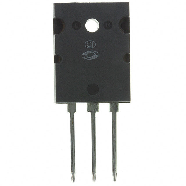
The APT60M75L2LLG is an N-Channel 600V 73A MOSFET manufactured by Microchip Technology in the POWER MOS 7® series. This device is housed in a TO-264-3 (264 MAX™ [L2]) through-hole package and is currently in Active product status. The APT60M75L2LLG delivers 893W maximum power dissipation and operates across the temperature range of -55°C to 150°C (TJ).
Equivalent and substitute parts are necessary when the primary part becomes unavailable, when alternative packaging or thermal characteristics better suit application requirements, or when design flexibility demands component options from different manufacturers while maintaining electrical and mechanical compatibility.
Substiute Parts
Key Parameters
| Parameter | Value | Unit |
|---|---|---|
| Drain to Source Voltage (Vdss) | 600 | V |
| Continuous Drain Current (Id) @ 25°C | 73 | A (Tc) |
| Rds On (Max) @ Id, Vgs | 75 mOhm @ 36.5A, 10V | mOhm |
| Gate Charge (Qg) (Max) @ Vgs | 195 | nC @ 10V |
| Power Dissipation (Max) | 893 | W (Tc) |
| Operating Temperature Range | -55 to 150 | °C (TJ) |
| Mounting Type | Through Hole | — |
| Package / Case | TO-264-3, TO-264AA | — |
| FET Type | N-Channel | — |
| Technology | MOSFET (Metal Oxide) | — |
Substitute Part Grouping Explanation
Substitution of the APT60M75L2LLG is determined by strict adherence to the following electrical and mechanical parameters:
Primary Substitution Criteria:
- Drain to Source Voltage (Vdss): 600V (exact match required)
- FET Type: N-Channel (exact match required)
- Technology: MOSFET (Metal Oxide) (exact match required)
- Continuous Drain Current (Id) @ 25°C: Equal to or greater than 73A
- Rds On (Max) @ Id, Vgs: Equal to or less than 75 mOhm @ 10V drive voltage
- Operating Temperature Range: -55°C to 150°C (TJ) minimum
- Mounting Type: Through Hole (exact match required)
- Package / Case: TO-264-3 or TO-264AA compatible footprints
Secondary Compatibility Factors:
- Gate Charge (Qg): Lower values preferred for faster switching; higher values acceptable if within thermal budget
- Power Dissipation (Max): Equal to or greater than 893W
- Vgs (Max): ±30V or greater (±20V minimum acceptable)
- Input Capacitance (Ciss): Variation acceptable within application switching frequency constraints
Substitute parts are grouped into two categories: Direct Equivalents (matching current and thermal specifications) and Compatible Alternatives (meeting voltage and current requirements with acceptable parameter variations).
Parameter Comparison
| Manufacturer Part Number | Manufacturer | Vdss (V) | Id @ 25°C (A) | Rds On (mOhm) | Qg (nC) | Pd Max (W) | Package | Product Status |
|---|---|---|---|---|---|---|---|---|
| APT60M75L2LLG | Microchip Technology | 600 | 73 | 75 @ 36.5A, 10V | 195 @ 10V | 893 | TO-264-3, TO-264AA | Active |
| IXFB82N60P | IXYS | 600 | 82 | 75 @ 41A, 10V | 240 @ 10V | 1250 | TO-264-3, TO-264AA | Active |
| IXFB82N60Q3 | IXYS | 600 | 82 | 75 @ 41A, 10V | 275 @ 10V | 1560 | TO-264-3, TO-264AA | Active |
| IXFK64N60P3 | IXYS | 600 | 64 | 95 @ 32A, 10V | 145 @ 10V | 1130 | TO-264-3, TO-264AA | Active |
| IXFK64N60Q3 | IXYS | 600 | 64 | 95 @ 32A, 10V | 190 @ 10V | 1250 | TO-264-3, TO-264AA | Active |
| IXFK80N60P3 | IXYS | 600 | 80 | 70 @ 500mA, 10V | 190 @ 10V | 1300 | TO-264-3, TO-264AA | Active |
| IXFL82N60P | IXYS | 600 | 55 | 78 @ 41A, 10V | 240 @ 10V | 625 | TO-264-3, TO-264AA | Active |
| FCH104N60 | onsemi | 600 | 37 | 104 @ 18.5A, 10V | 82 @ 10V | 357 | TO-247-3 | Obsolete |
| FCH104N60F-F085 | onsemi | 600 | 37 | 104 @ 18.5A, 10V | 139 @ 10V | 357 | TO-247-3 | Not For New Designs |
| STW48N60M2 | STMicroelectronics | 600 | 42 | 70 @ 21A, 10V | 70 @ 10V | 300 | TO-247-3 | Active |
Engineering Selection Recommendations
Direct Equivalents (Recommended for Primary Selection):
The IXFB82N60P and IXFB82N60Q3 from IXYS are the closest functional equivalents to the APT60M75L2LLG. Both devices maintain 600V Vdss, exceed the 73A continuous drain current requirement with 82A ratings, match the 75 mOhm Rds On specification, and are housed in compatible TO-264-3/TO-264AA packages. Both parts are in Active product status. The IXFB82N60Q3 offers enhanced thermal performance (1560W vs. 1250W) and is classified as Q3 Class, providing superior reliability margins. The IXFB82N60P is suitable for applications where standard thermal performance is adequate.
Compatible Alternatives (Secondary Selection):
The IXFK80N60P3 provides 80A continuous drain current with 70 mOhm Rds On, delivering superior current handling and lower on-resistance compared to the primary part. This device is suitable for applications requiring enhanced performance headroom. The IXFK64N60P3 and IXFK64N60Q3 offer 64A current ratings with acceptable Rds On values of 95 mOhm, appropriate for applications where the 73A requirement can be reduced. Both IXFK devices are in Active status and use compatible TO-264-3/TO-264AA packaging.
Limited Substitution (Not Recommended for New Designs):
The FCH104N60 and FCH104N60F-F085 from onsemi meet the 600V voltage requirement but fall short of the 73A current specification with only 37A ratings. The FCH104N60 is Obsolete, and the FCH104N60F-F085 is marked Not For New Designs. These parts are suitable only for legacy system maintenance where current requirements can be verified as lower than specified.
The STW48N60M2 from STMicroelectronics provides 42A continuous drain current, which is insufficient for the 73A requirement of the primary part. This device is not suitable as a substitute.
Compliance and Certification:
All recommended substitute parts (IXFB82N60P, IXFB82N60Q3, IXFK80N60P3, IXFK64N60P3, IXFK64N60Q3) are RoHS3 Compliant, REACH Unaffected, and classified under ECCN EAR99. The FCH104N60F-F085 carries AEC-Q101 automotive qualification, suitable for automotive applications requiring this certification. All parts maintain Moisture Sensitivity Level 1 (Unlimited) or equivalent, ensuring compatibility with standard handling and storage procedures.
Frequently Asked Questions (FAQ)
Q: Can the IXFK64N60P3 substitute for the APT60M75L2LLG in all applications?
A: The IXFK64N60P3 meets the 600V voltage requirement and operates within the same temperature range. However, its 64A continuous drain current rating is below the 73A specification of the primary part. Substitution is valid only if circuit analysis confirms that actual operating current does not exceed 64A. The 95 mOhm Rds On is higher than the 75 mOhm specification, resulting in increased power dissipation at equivalent current levels.
Q: What is the primary advantage of the IXFB82N60Q3 over the IXFB82N60P?
A: Both devices share identical electrical specifications (600V, 82A, 75 mOhm Rds On). The IXFB82N60Q3 is classified as Q3 Class and delivers 1560W maximum power dissipation compared to 1250W for the standard IXFB82N60P. The Q3 Class designation indicates enhanced reliability and tighter parameter control, providing superior thermal performance and design margin for high-power applications.
Q: Are the onsemi FCH104N60 parts suitable replacements?
A: The FCH104N60 and FCH104N60F-F085 are not suitable as direct replacements. Both are rated for only 37A continuous drain current, which is 50% below the 73A requirement. Additionally, the FCH104N60 is Obsolete and the FCH104N60F-F085 is marked Not For New Designs. These parts are acceptable only for legacy system repairs where actual operating current has been verified to remain below 37A.
Q: Can I use the STW48N60M2 as a substitute?
A: No. The STW48N60M2 is rated for 42A continuous drain current, which is insufficient for the 73A specification. Although it meets the 600V voltage requirement and operates within the same temperature range, the current rating deficit makes it unsuitable for direct substitution.
Q: What is the difference between TO-264-3 and TO-264AA packaging?
A: TO-264-3 and TO-264AA are equivalent package designations for the same physical form factor. Both refer to a three-lead through-hole package with identical pin spacing and mounting footprint. Devices specified as compatible with either TO-264-3 or TO-264AA can be used interchangeably on the same PCB layout.
Q: Why do some substitute parts have higher gate charge (Qg) values?
A: Gate charge variation reflects differences in internal device structure and manufacturing process between manufacturers. Higher Qg values require longer gate drive times and increased driver power consumption but do not affect DC electrical performance. Substitution is valid provided the gate driver circuit can supply the required charge within acceptable switching frequency constraints.
Q: Is the IXFL82N60P a suitable substitute despite its lower current rating?
A: The IXFL82N60P is rated for 55A continuous drain current, which is below the 73A requirement. Although it matches the 600V voltage specification and uses compatible TO-264-3/TO-264AA packaging, the current rating deficit makes it unsuitable for applications requiring the full 73A capability. Substitution is valid only if circuit analysis confirms that actual operating current remains below 55A.
Q: What compliance certifications should I verify for automotive applications?
A: For automotive applications, verify AEC-Q101 qualification. The FCH104N60F-F085 carries this certification. The primary part (APT60M75L2LLG) and most IXYS substitute parts do not list AEC-Q101 qualification in the provided specifications. If automotive qualification is mandatory, the FCH104N60F-F085 is the only listed option, though its 37A current rating is insufficient for the primary application.
Q: Can I parallel multiple lower-current devices to achieve the 73A requirement?
A: Paralleling is not addressed in this substitution reference. Parallel device operation requires detailed thermal analysis, current sharing verification, and gate drive circuit redesign. Consult device datasheets and application notes for paralleling guidelines specific to each manufacturer's technology.
Alternative Parts

SJ6012L2TP
Littelfuse Inc.
6 Alternative Parts

JMK107BBJ476MA-RE
Taiyo Yuden
10 Alternative Parts

GMK107BBJ475MA-T
Taiyo Yuden
5 Alternative Parts
SJ6020N2ARP
Littelfuse Inc.
3 Alternative Parts
SJ6025R2ATP
Littelfuse Inc.
4 Alternative Parts

2474-05L
API Delevan Inc.
1 Alternative Parts

4590R-684K
API Delevan Inc.
1 Alternative Parts

CM6560R-334
API Delevan Inc.
1 Alternative Parts

CM6460-104
API Delevan Inc.
1 Alternative Parts

5526-12
API Delevan Inc.
1 Alternative Parts