


Request Quote
(Ships tomorrow)
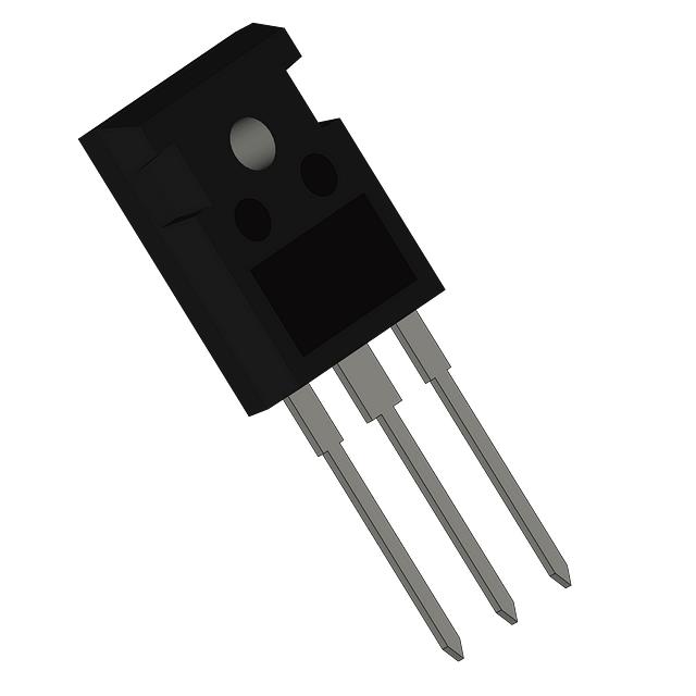
APT34F60B N-Channel 600V 36A MOSFET Equivalent & Substitute Parts
Part Overview
The APT34F60B is an N-Channel MOSFET manufactured by Microchip Technology, rated for 600V drain-to-source voltage with 36A continuous drain current at 25°C. The device is housed in a TO-247-3 package and is designed for through-hole mounting applications requiring high-voltage switching capability. This part is currently in Active product status with 1334 units in stock.
Substitute parts are identified when equivalent electrical performance can be achieved within the specified parameter tolerances while maintaining the same package type and thermal characteristics. The following substitute devices meet the core electrical and mechanical requirements for direct replacement or application-specific alternatives.
Substiute Parts
Key Parameters
| Parameter | Value | Unit | Specification Basis |
|---|---|---|---|
| Drain-to-Source Voltage (Vdss) | 600 | V | Maximum rated voltage |
| Continuous Drain Current (Id) @ 25°C | 36 | A | Thermal case temperature |
| On-State Resistance (Rds On) @ 17A, 10V | 210 | mOhm | Maximum at specified gate voltage |
| Gate Threshold Voltage (Vgs(th)) @ 1mA | 5 | V | Maximum threshold |
| Gate Charge (Qg) @ 10V | 165 | nC | Maximum switching charge |
| Power Dissipation (Max) | 624 | W | Thermal case temperature rating |
| Operating Temperature Range | -55 to 150 | °C | Junction temperature |
| Package Type | TO-247-3 | — | Through-hole mounting |
| RoHS Compliance | ROHS3 Compliant | — | Environmental standard |
Substitute Part Grouping Explanation
Substitute parts are classified based on the following electrical and mechanical criteria derived from the APT34F60B specifications:
Primary Substitution Criteria:
- Drain-to-Source Voltage (Vdss): 600V minimum (allows up to 650V for higher voltage margin)
- Continuous Drain Current (Id): 20A minimum (APT34F60B rated at 36A; lower-current devices acceptable for reduced-load applications)
- On-State Resistance (Rds On): Maximum 210mOhm at specified gate voltage (lower values preferred for reduced power loss)
- Gate Threshold Voltage (Vgs(th)): 3.5V to 5.5V range (ensures compatible gate drive requirements)
- Package Type: TO-247-3 or equivalent through-hole configuration
- Operating Temperature: -55°C to 150°C minimum (matches thermal envelope)
- RoHS Compliance: ROHS3 Compliant (environmental requirement)
Substitution Logic: Devices with Vdss ≥ 600V and Id ≥ 20A are considered functionally equivalent for most applications. Rds On values within ±50mOhm of the main part allow for thermal performance variations. Gate charge and input capacitance variations are acceptable provided gate drive circuitry can accommodate the specified Vgs(th) range.
Parameter Comparison
| Part Number | Manufacturer | Vdss (V) | Id @ 25°C (A) | Rds On (mOhm) | Vgs(th) (V) | Qg (nC) | Power Diss. (W) | Status |
|---|---|---|---|---|---|---|---|---|
| APT34F60B | Microchip Technology | 600 | 36 | 210 @ 17A, 10V | 5 @ 1mA | 165 @ 10V | 624 | Active |
| FCH150N65F-F155 | onsemi | 650 | 24 | 150 @ 12A, 10V | 5 @ 2.4mA | 94 @ 10V | 298 | Not For New Designs |
| FCH165N60E | onsemi | 600 | 23 | 165 @ 11.5A, 10V | 3.5 @ 250µA | 75 @ 10V | 227 | Not For New Designs |
| FCH170N60 | Fairchild Semiconductor | 600 | 22 | 170 @ 11A, 10V | 3.5 @ 250µA | 55 @ 10V | 227 | Active |
| IXFH30N60X | IXYS | 600 | 30 | 155 @ 15A, 10V | 4.5 @ 4mA | 56 @ 10V | 500 | Obsolete |
| IXFH50N60P3 | IXYS | 600 | 50 | 145 @ 500mA, 10V | 5 @ 4mA | 94 @ 10V | 1040 | Active |
| IXTH20N65X | IXYS | 650 | 20 | 210 @ 10A, 10V | 5.5 @ 250µA | 35 @ 10V | 320 | Last Time Buy |
| R6024KNZ1C9 | Rohm Semiconductor | 600 | 24 | 165 @ 11.3A, 10V | 5 @ 1mA | 45 @ 10V | 245 | Obsolete |
| SPW17N80C3FKSA1 | Infineon Technologies | 800 | 17 | 290 @ 11A, 10V | 3.9 @ 1mA | 177 @ 10V | 227 | Active |
| STW18N65M5 | STMicroelectronics | 650 | 15 | 220 @ 7.5A, 10V | 5 @ 250µA | 31 @ 10V | 110 | Active |
| STW24N60DM2 | STMicroelectronics | 600 | 18 | 200 @ 9A, 10V | 5 @ 250µA | 29 @ 10V | 150 | Active |
Engineering Selection Recommendations
Primary Substitutes (Active Status, Direct Replacement Capability):
IXFH50N60P3 (IXYS) is the closest electrical equivalent with 50A continuous drain current, exceeding the APT34F60B rating. This device provides superior current handling and thermal performance (1040W dissipation) while maintaining 600V Vdss and TO-247-3 packaging. Product status is Active with full availability. Rds On of 145mOhm is lower than the main part, resulting in reduced conduction losses.
FCH170N60 (Fairchild Semiconductor) operates at 600V with 22A continuous current and 170mOhm Rds On. This device is suitable for applications where current requirements are reduced. Product status is Active. Gate threshold of 3.5V requires verification against existing gate drive circuitry.
STW24N60DM2 (STMicroelectronics) provides 600V, 18A continuous current with 200mOhm Rds On. Product status is Active with full RoHS3 compliance. Lower power dissipation (150W) indicates suitability for reduced-load applications.
Secondary Substitutes (Higher Voltage Rating, Reduced Current):
IXTH20N65X (IXYS) offers 650V Vdss with 20A continuous current. Product status is Last Time Buy, indicating limited future availability. Rds On matches the main part at 210mOhm. This device is suitable for applications requiring higher voltage margin.
STW18N65M5 (STMicroelectronics) provides 650V with 15A continuous current. Product status is Active. Lower current rating restricts use to reduced-load applications.
Not Recommended for New Designs:
FCH150N65F-F155 and FCH165N60E (onsemi) carry "Not For New Designs" status, indicating manufacturer discontinuation trajectory. These devices should not be selected for new product development.
Obsolete Devices:
IXFH30N60X (IXYS) and R6024KNZ1C9 (Rohm Semiconductor) are marked Obsolete and Last Time Buy respectively. These parts should not be used in new designs due to supply uncertainty.
Higher Voltage Alternative:
SPW17N80C3FKSA1 (Infineon Technologies CoolMOS™) operates at 800V with 17A continuous current. This device is suitable only for applications requiring higher voltage margin with reduced current requirements. Product status is Active. Rds On of 290mOhm is significantly higher, resulting in increased conduction losses compared to the main part.
Frequently Asked Questions (FAQ)
Q1: Can I use IXFH50N60P3 as a direct replacement for APT34F60B?
A: Yes, IXFH50N60P3 is electrically compatible. Both devices operate at 600V with TO-247-3 packaging and -55°C to 150°C temperature range. IXFH50N60P3 provides higher current capability (50A vs. 36A) and lower Rds On (145mOhm vs. 210mOhm), resulting in improved thermal performance. Verify PCB layout and thermal management are adequate for the higher power dissipation capability (1040W vs. 624W).
Q2: What is the minimum drain current rating acceptable for substitution?
A: Substitute devices with continuous drain current of 20A or higher are considered functionally equivalent for most applications. Lower-current devices (15A to 18A range) are acceptable only if application load analysis confirms reduced current requirements. Gate drive circuitry must be verified for compatibility with the substitute device's Vgs(th) specification.
Q3: Are 650V-rated devices acceptable replacements for the 600V APT34F60B?
A: Yes, 650V-rated devices provide higher voltage margin and are electrically compatible. Devices such as FCH150N65F-F155, IXTH20N65X, and STW18N65M5 operate safely in 600V applications. However, verify that the substitute device's Rds On and gate charge specifications are compatible with existing gate drive circuitry.
Q4: Why is SPW17N80C3FKSA1 listed as a substitute if it operates at 800V?
A: SPW17N80C3FKSA1 is listed as a substitute for applications requiring higher voltage margin beyond 600V. This device is not recommended as a direct replacement due to significantly reduced current rating (17A vs. 36A) and higher Rds On (290mOhm vs. 210mOhm). Use this device only in applications with reduced current requirements and higher voltage stress conditions.
Q5: What is the impact of Rds On variation on thermal performance?
A: On-state resistance directly affects conduction losses. Lower Rds On values reduce power dissipation and junction temperature rise. For example, IXFH50N60P3 with 145mOhm Rds On generates less heat than APT34F60B at 210mOhm. Conversely, SPW17N80C3FKSA1 at 290mOhm generates significantly more heat. Thermal analysis must account for Rds On differences when selecting substitutes.
Q6: Can I use devices marked "Not For New Designs" in existing production?
A: Devices marked "Not For New Designs" (FCH150N65F-F155, FCH165N60E) are electrically compatible but should not be selected for new product development. These parts may be used for legacy product support or repair applications where supply is available. Verify long-term availability with the manufacturer before committing to production use.
Q7: What gate drive voltage compatibility should I verify?
A: Gate threshold voltage (Vgs(th)) ranges from 3.5V to 5.5V across substitute devices. APT34F60B specifies 5V @ 1mA. Devices with lower Vgs(th) (3.5V to 3.9V) may require gate drive circuit adjustment. Verify that existing gate drive circuitry can reliably turn on and off the substitute device across the specified Vgs(th) range and operating temperature extremes (-55°C to 150°C).
Q8: Are all substitute parts RoHS3 compliant?
A: Yes, all listed substitute devices are RoHS3 compliant, matching the environmental compliance requirement of APT34F60B. REACH status is "REACH Unaffected" for all devices, confirming no restricted substances are present.
Q9: What is the significance of gate charge (Qg) differences?
A: Gate charge affects switching speed and gate drive power requirements. APT34F60B specifies 165nC @ 10V. Lower gate charge values (29nC to 94nC) reduce gate drive losses and allow faster switching. Higher gate charge (177nC for SPW17N80C3FKSA1) increases gate drive power consumption. Verify gate drive circuitry can supply adequate current for the substitute device's gate charge specification.
Q10: Which substitute offers the best thermal performance?
A: IXFH50N60P3 offers the best thermal performance with 1040W maximum power dissipation and 145mOhm Rds On. This device is suitable for high-current applications where thermal management is critical. For reduced-load applications, STW24N60DM2 provides adequate thermal performance with lower power dissipation (150W) and is suitable for space-constrained designs.
Alternative Parts

SJ6012L2TP
Littelfuse Inc.
6 Alternative Parts

JMK107BBJ476MA-RE
Taiyo Yuden
10 Alternative Parts

GMK107BBJ475MA-T
Taiyo Yuden
5 Alternative Parts
SJ6020N2ARP
Littelfuse Inc.
3 Alternative Parts
SJ6025R2ATP
Littelfuse Inc.
4 Alternative Parts

2474-05L
API Delevan Inc.
1 Alternative Parts

4590R-684K
API Delevan Inc.
1 Alternative Parts

CM6560R-334
API Delevan Inc.
1 Alternative Parts

CM6460-104
API Delevan Inc.
1 Alternative Parts

5526-12
API Delevan Inc.
1 Alternative Parts