


Request Quote
(Ships tomorrow)
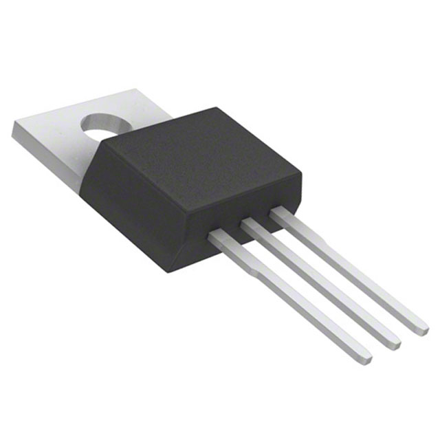
AOT7S65L N-Channel 650V 7A MOSFET TO-220 Equivalent & Substitute Parts
Part Overview
The AOT7S65L is an N-Channel metal oxide semiconductor field-effect transistor (MOSFET) manufactured by Alpha & Omega Semiconductor Inc., rated for 650V drain-to-source voltage and 7A continuous drain current in a through-hole TO-220 package. This device is classified as "Not For New Designs," indicating it has reached end-of-life status. The aMOS™ series transistor is designed for high-voltage switching applications requiring robust performance across industrial and power conversion circuits.
Due to its obsolete product status, equivalent and substitute parts are necessary for ongoing maintenance, repair, and legacy system support. Substitute devices must maintain electrical compatibility within the specified parameter ranges while accommodating available alternatives from active product lines.
Substiute Parts
Key Parameters
| Parameter | Value | Unit |
|---|---|---|
| Drain-to-Source Voltage (Vdss) | 650 | V |
| Continuous Drain Current (Id) @ 25°C | 7 | A |
| On-State Resistance (Rds On) @ 3.5A, 10V | 650 | mOhm |
| Gate-Source Threshold Voltage (Vgs(th)) @ 250µA | 4 | V |
| Gate Charge (Qg) @ 10V | 9.2 | nC |
| Input Capacitance (Ciss) @ 100V | 434 | pF |
| Power Dissipation (Max) | 104 | W |
| Operating Temperature Range | -55 to 150 | °C |
| Package Type | TO-220-3 | Through Hole |
| FET Type | N-Channel | — |
Substitute Part Grouping Explanation
Substitution of the AOT7S65L is determined by strict adherence to the following electrical and mechanical parameters:
Primary Substitution Criteria:
- FET Type: N-Channel topology required
- Package: TO-220-3 through-hole configuration mandatory
- Drain-to-Source Voltage (Vdss): Minimum 650V to maintain voltage margin
- Continuous Drain Current (Id): Minimum 7A at 25°C to support load requirements
- Gate-Source Voltage (Vgs): ±30V maximum rating or compatible
- Operating Temperature: -55°C to 150°C range required
Secondary Compatibility Parameters:
- On-State Resistance (Rds On): Values within 620–900 mOhm acceptable for thermal performance equivalence
- Gate Charge (Qg): Values between 9.2–55 nC compatible with drive circuit timing
- Input Capacitance (Ciss): Values between 315–2200 pF acceptable for switching characteristics
- Power Dissipation: Minimum 85W to support thermal load
Substitute parts are grouped into two categories: Direct Equivalents (matching voltage and current ratings) and Functional Alternatives (higher voltage or current ratings suitable for drop-in replacement with equivalent or improved performance).
Parameter Comparison
| Part Number | Manufacturer | Vdss (V) | Id @ 25°C (A) | Rds On (mOhm) | Qg (nC) | Ciss (pF) | Pd Max (W) | Status |
|---|---|---|---|---|---|---|---|---|
| AOT7S65L | Alpha & Omega | 650 | 7 | 650 @ 3.5A | 9.2 | 434 | 104 | Not For New Designs |
| STP11N65M2 | STMicroelectronics | 650 | 7 | 670 @ 3.5A | 12.5 | 410 | 85 | Active |
| STP9N65M2 | STMicroelectronics | 650 | 5 | 900 @ 2.5A | 10 | 315 | 60 | Active |
| STP10N95K5 | STMicroelectronics | 950 | 8 | 800 @ 4A | 22 | 630 | 130 | Active |
| IRFB9N60APBF | Vishay Siliconix | 600 | 9.2 | 750 @ 5.5A | 49 | 1400 | 170 | Active |
| IXFP10N60P | IXYS | 600 | 10 | 740 @ 5A | 32 | 1610 | 200 | Active |
| APT12F60K | Microsemi | 600 | 12 | 620 @ 6A | 55 | 2200 | 225 | Active |
| FDP12N60NZ | onsemi | 600 | 12 | 650 @ 6A | 34 | 1676 | 240 | Obsolete |
| FCP650N80Z | onsemi | 800 | 10 | 650 @ 4A | 35 | 1565 | 162 | Obsolete |
Engineering Selection Recommendations
Direct Equivalent (Preferred for Drop-In Replacement):
STP11N65M2 (STMicroelectronics) is the primary equivalent substitute. It maintains identical voltage (650V) and current (7A) ratings with comparable on-state resistance (670 mOhm vs. 650 mOhm). The device is in Active product status, ensuring long-term availability and supply chain continuity. Gate charge (12.5 nC) and input capacitance (410 pF) are within acceptable switching characteristic ranges. RoHS3 compliance and unlimited moisture sensitivity level (MSL 1) match the original specification.
Functional Alternative (Higher Performance Margin):
STP10N95K5 (STMicroelectronics) provides enhanced voltage margin at 950V with 8A continuous current, suitable for applications requiring additional voltage headroom. The SuperMESH5™ technology delivers improved thermal performance (130W) and lower gate charge (22 nC), enabling faster switching. This device is Active and RoHS3 compliant.
Current-Enhanced Alternatives (Higher Current Rating):
APT12F60K (Microsemi), IXFP10N60P (IXYS), and IRFB9N60APBF (Vishay Siliconix) offer 9.2A to 12A continuous current ratings at reduced voltage (600V). These devices are suitable for applications where voltage margin can be reduced in exchange for higher current capacity. All three are Active products with RoHS3 compliance.
Avoid:
FDP12N60NZ and FCP650N80Z are classified as Obsolete and should not be selected for new applications or long-term system support, despite electrical compatibility.
Frequently Asked Questions (FAQ)
Q: Can STP11N65M2 directly replace AOT7S65L without circuit modification?
A: Yes. STP11N65M2 maintains identical voltage (650V) and current (7A) ratings with equivalent on-state resistance (670 mOhm vs. 650 mOhm). The TO-220-3 package is mechanically identical. Gate charge and input capacitance are within acceptable ranges for existing drive circuits. No circuit modification is required.
Q: What is the voltage difference between 650V and 600V rated devices, and does it affect substitution?
A: Devices rated 600V (IRFB9N60APBF, IXFP10N60P, APT12F60K) have 50V lower maximum voltage rating than the 650V original. These are acceptable substitutes only if the application circuit operates below 600V. For circuits operating near 650V, use 650V or higher rated devices (STP11N65M2, STP10N95K5).
Q: Why does STP9N65M2 have lower current (5A) than the original (7A)?
A: STP9N65M2 is rated for 5A continuous current, below the 7A requirement of AOT7S65L. This device is not suitable as a direct substitute for applications requiring 7A. It may be used only in circuits with reduced current demand.
Q: Are all substitute parts RoHS3 compliant?
A: Yes. All listed substitute parts carry RoHS3 Compliant certification, matching the original AOT7S65L specification. REACH status varies: IRFB9N60APBF is REACH Affected; all others are REACH Unaffected.
Q: What is the significance of gate charge (Qg) differences between parts?
A: Gate charge determines the energy required to switch the transistor on and off. The original AOT7S65L has 9.2 nC gate charge. Substitutes range from 10 nC to 55 nC. Higher gate charge requires more drive current from the gate driver circuit. Devices with significantly higher gate charge (APT12F60K at 55 nC) may require gate driver circuit verification to ensure adequate drive capability.
Q: Can I use a 950V rated device (STP10N95K5) in a 650V application?
A: Yes. Higher voltage rating provides additional safety margin. STP10N95K5 at 950V is suitable for 650V applications. The higher voltage rating does not degrade performance; it only increases the maximum safe operating voltage. This device is preferred when voltage margin is a design concern.
Q: What is the difference between TO-220 and TO-220-3 package designations?
A: TO-220-3 is the standard three-lead through-hole package (Gate, Drain, Source). All listed parts use TO-220-3 configuration. The designation is functionally equivalent across manufacturers. Physical mounting and lead spacing are identical.
Q: Why is APT12F60K rated for 12A when the original is only 7A?
A: APT12F60K is designed for higher current applications. The 12A rating reflects the device's thermal and electrical capability. In a 7A application, this device operates well below its maximum rating, providing thermal margin and extended component life. The trade-off is reduced voltage rating (600V vs. 650V).
Q: Are Obsolete parts (FDP12N60NZ, FCP650N80Z) acceptable for repair applications?
A: Obsolete parts should be avoided for new designs and long-term system support due to uncertain future availability. For immediate repair of legacy equipment, Obsolete parts may be used only if Active alternatives are unavailable and existing inventory is confirmed. Preference should be given to Active status devices for sustained supply chain reliability.
Alternative Parts

SJ6012L2TP
Littelfuse Inc.
6 Alternative Parts

JMK107BBJ476MA-RE
Taiyo Yuden
10 Alternative Parts

GMK107BBJ475MA-T
Taiyo Yuden
5 Alternative Parts
SJ6020N2ARP
Littelfuse Inc.
3 Alternative Parts
SJ6025R2ATP
Littelfuse Inc.
4 Alternative Parts

2474-05L
API Delevan Inc.
1 Alternative Parts

4590R-684K
API Delevan Inc.
1 Alternative Parts

CM6560R-334
API Delevan Inc.
1 Alternative Parts

CM6460-104
API Delevan Inc.
1 Alternative Parts

5526-12
API Delevan Inc.
1 Alternative Parts