


Request Quote
(Ships tomorrow)
AOT482L N-Channel 80V 11A/105A MOSFET TO-220 Equivalent & Substitute Parts
Part Overview
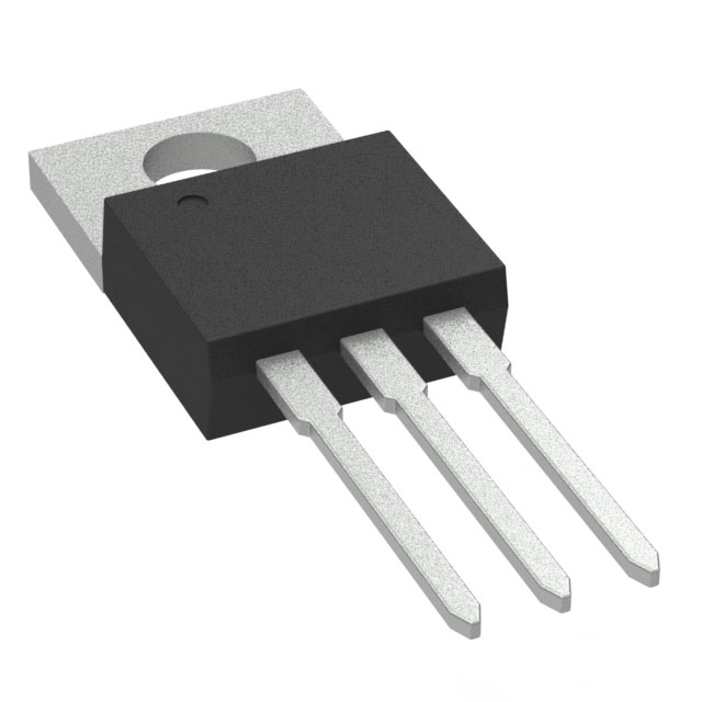
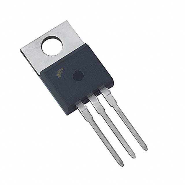
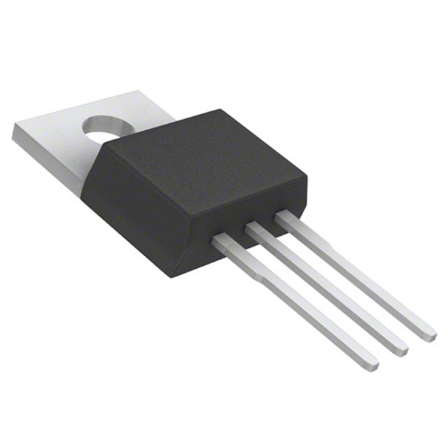
The AOT482L is an N-Channel MOSFET manufactured by Alpha & Omega Semiconductor Inc., rated for 80V drain-to-source voltage with continuous drain current of 11A at Ta and 105A at Tc in a Through Hole TO-220 package. This device is classified as Not For New Designs, indicating it has reached end-of-life status. Identification of equivalent and substitute parts is necessary for ongoing production support, field repairs, and design continuity where the AOT482L is currently deployed.
Substiute Parts
Key Parameters
| Parameter | Value | Unit |
|---|---|---|
| Drain-to-Source Voltage (Vdss) | 80 | V |
| Continuous Drain Current @ 25°C (Ta) | 11 | A |
| Continuous Drain Current @ 25°C (Tc) | 105 | A |
| RDS(on) Max @ 20A, 10V | 7.2 | mOhm |
| Gate Threshold Voltage (Vgs(th)) @ 250µA | 3.7 | V |
| Gate Charge (Qg) @ 10V | 81 | nC |
| Input Capacitance (Ciss) @ 40V | 4870 | pF |
| Power Dissipation (Ta) | 2.1 | W |
| Power Dissipation (Tc) | 333 | W |
| Operating Temperature Range | -55 to 175 | °C |
| Package Type | TO-220-3 | Through Hole |
| FET Type | N-Channel | — |
| Technology | MOSFET (Metal Oxide) | — |
Substitute Part Grouping Explanation
Substitution of the AOT482L is determined by the following critical parameters:
Voltage Rating Compatibility: The Vdss of 80V is the primary constraint. Substitute parts must equal or exceed 80V to maintain circuit protection margins. Parts rated at 100V are acceptable as they provide additional voltage headroom.
Current Handling Capability: The continuous drain current specification (11A Ta, 105A Tc) establishes the minimum current capacity required. Substitute parts must support equivalent or higher current ratings to ensure thermal and electrical performance parity.
On-Resistance (RDS(on)): The maximum on-resistance of 7.2 mOhm at 20A, 10V defines conduction losses. Substitute parts with equal or lower RDS(on) values maintain or improve efficiency characteristics.
Gate Charge and Input Capacitance: These parameters affect switching speed and gate drive requirements. Substitute parts with comparable or lower values ensure compatibility with existing gate drive circuits.
Thermal Performance: Power dissipation ratings (2.1W Ta, 333W Tc) and operating temperature range (-55°C to 175°C) must be maintained or exceeded.
Package and Mounting: All substitutes must be Through Hole TO-220-3 configuration to ensure mechanical and thermal interface compatibility.
Compliance and Status: RoHS3 compliance and product status (Active vs. Not For New Designs) are documented for procurement and regulatory purposes.
Parameter Comparison
| Part Number | Manufacturer | Vdss (V) | Id @ 25°C (A) | RDS(on) Max (mOhm) | Vgs(th) (V) | Qg (nC) | Ciss (pF) | Pd Tc (W) | Status | Package |
|---|---|---|---|---|---|---|---|---|---|---|
| AOT482L | Alpha & Omega | 80 | 105 (Tc) | 7.2 | 3.7 | 81 | 4870 | 333 | Not For New Designs | TO-220-3 |
| AOT286L | Alpha & Omega | 80 | 70 (Tc) | 6.0 | 3.3 | 63 | 3142 | 167 | Active | TO-220-3 |
| CSD19501KCS | Texas Instruments | 80 | 100 (Ta) | 6.6 | 3.2 | 50 | 3980 | 217 | Active | TO-220-3 |
| FDP054N10 | onsemi | 100 | 120 (Tc) | 5.5 | 4.5 | 203 | 13280 | 263 | Active | TO-220-3 |
| IPP80N08S406AKSA1 | Infineon | 80 | 80 (Tc) | 5.8 | 4.0 | 70 | 4800 | 150 | Last Time Buy | TO-220-3 |
| IRF3808PBF | Infineon | 75 | 140 (Tc) | 7.0 | 4.0 | 220 | 5310 | 330 | Active | TO-220-3 |
| IXFP180N10T2 | IXYS | 100 | 180 (Tc) | 6.0 | 4.0 | 185 | 10500 | 480 | Active | TO-220-3 |
| IXTP160N10T | IXYS | 100 | 160 (Tc) | 7.0 | 4.5 | 132 | 6600 | 430 | Active | TO-220-3 |
| IXTP180N10T | IXYS | 100 | 180 (Tc) | 6.4 | 4.5 | 151 | 6900 | 480 | Active | TO-220-3 |
| PSMN6R5-80PS,127 | Nexperia | 80 | 100 (Tc) | 6.9 | 4.0 | 71 | 4461 | 210 | Obsolete | TO-220-3 |
Engineering Selection Recommendations
Primary Substitutes (Same Voltage Rating, Active Status):
The CSD19501KCS (Texas Instruments NexFET™) and AOT286L (Alpha & Omega) are the preferred substitutes for the AOT482L. Both devices maintain the 80V Vdss rating, support continuous drain currents within the operational envelope of the original part, and carry Active product status. The CSD19501KCS offers superior gate charge characteristics (50 nC vs. 81 nC) and lower RDS(on) (6.6 mOhm vs. 7.2 mOhm), resulting in reduced switching losses and improved thermal performance. The AOT286L, from the same manufacturer as the original part, provides design continuity and is available in high inventory quantities (10,126 pieces).
Secondary Substitutes (Higher Voltage Rating, Active Status):
The IXTP180N10T, IXTP160N10T, and IXFP180N10T2 (IXYS) and FDP054N10 (onsemi) are rated at 100V Vdss, providing additional voltage margin. These parts support significantly higher continuous drain currents (160A to 180A Tc) and deliver superior power dissipation capabilities (430W to 480W Tc). These devices are suitable for applications where voltage headroom and thermal performance are critical. The higher gate charge values (132 nC to 203 nC) require verification of gate drive circuit compatibility.
Avoid:
The IPP80N08S406AKSA1 (Infineon OptiMOS™) carries Last Time Buy status, indicating imminent discontinuation. The PSMN6R5-80PS,127 (Nexperia) is classified as Obsolete and should not be selected for new applications or long-term production support.
Compliance Verification:
All recommended substitutes are RoHS3 compliant and REACH unaffected, matching the regulatory status of the AOT482L. The IPP80N08S406AKSA1 carries AEC-Q101 automotive qualification, suitable for applications requiring automotive-grade components.
Frequently Asked Questions (FAQ)
Q: Can the AOT286L directly replace the AOT482L in existing designs?
A: The AOT286L is electrically compatible with the AOT482L for most applications. Both devices share the same 80V Vdss rating, TO-220-3 package, and operating temperature range. The AOT286L exhibits lower RDS(on) (6.0 mOhm vs. 7.2 mOhm) and reduced gate charge (63 nC vs. 81 nC), resulting in improved efficiency. The continuous drain current at Tc is lower (70A vs. 105A), which must be verified against circuit requirements. No PCB modifications are required.
Q: What is the difference between Ta and Tc current ratings?
A: Ta (ambient temperature) and Tc (case temperature) represent different measurement conditions. The Ta rating (11A for AOT482L) reflects performance at 25°C ambient with natural convection. The Tc rating (105A for AOT482L) reflects performance at 25°C case temperature with active cooling or thermal management. Circuit design must account for the applicable thermal conditions and select parts with sufficient current capacity under the expected operating environment.
Q: Why do some substitutes have higher Vdss ratings (100V vs. 80V)?
A: Higher voltage ratings provide additional circuit protection margin against transient overvoltages and voltage spikes. A 100V-rated device in an 80V circuit operates with 20% voltage headroom, improving reliability and component longevity. This is a conservative design practice. However, higher voltage ratings typically result in increased on-resistance and gate charge, which may affect switching performance and thermal characteristics.
Q: Are the IXYS Trench devices (IXTP160N10T, IXTP180N10T) suitable for the AOT482L application?
A: The IXYS Trench devices are electrically compatible substitutes with 100V Vdss ratings and significantly higher current capacity (160A to 180A Tc). These parts are suitable if the circuit can accommodate the higher gate charge (132 nC to 151 nC) and input capacitance (6600 pF to 6900 pF). Gate drive circuit verification is required to confirm adequate drive voltage and current capability. The superior thermal performance (430W to 480W Tc) makes these devices advantageous for high-power applications.
Q: What is the significance of the "Last Time Buy" status for the IPP80N08S406AKSA1?
A: Last Time Buy status indicates that the manufacturer has announced end-of-life for the device and will accept orders only until a specified cutoff date. After this date, the part will no longer be available. The IPP80N08S406AKSA1 should not be selected for new designs or applications requiring long-term production support. Existing inventory may be available for field repairs or legacy system support, but alternative parts should be qualified for future production.
Q: Can the IRF3808PBF (75V rating) be used in place of the AOT482L (80V rating)?
A: The IRF3808PBF is rated at 75V Vdss, which is 5V lower than the AOT482L. This device is not recommended as a direct substitute because it provides reduced voltage margin and may not meet circuit protection requirements if transient overvoltages exceed 75V. However, the IRF3808PBF offers higher continuous drain current (140A Tc) and is available in high inventory quantities (53,400 pieces). Use of this device requires circuit analysis to confirm that maximum voltage stress remains below 75V under all operating and fault conditions.
Q: Are all substitute parts available in the same TO-220-3 package?
A: Yes, all substitute parts listed are available in Through Hole TO-220-3 package configuration. This ensures mechanical and thermal interface compatibility with existing PCB designs. No modifications to PCB footprints, mounting hardware, or thermal management systems are required. Pin assignments (Gate, Drain, Source) follow standard TO-220-3 conventions across all listed devices.
Q: What gate drive voltage is required for these N-Channel MOSFETs?
A: All listed devices specify maximum gate-source voltage (Vgs) of ±20V to ±30V. Gate threshold voltages (Vgs(th)) range from 3.2V to 4.5V at 250µA. Standard gate drive circuits rated for 10V to 15V gate voltage are compatible with all substitutes. The gate charge values (50 nC to 220 nC) determine the gate drive current and switching speed. Higher gate charge values require proportionally higher gate drive current to achieve equivalent switching performance.
Q: Is the CSD19501KCS suitable for high-frequency switching applications?
A: The CSD19501KCS exhibits favorable characteristics for high-frequency operation, including low gate charge (50 nC), low input capacitance (3980 pF), and low RDS(on) (6.6 mOhm). These parameters result in reduced switching losses and improved efficiency at elevated switching frequencies. The device is part of the Texas Instruments NexFET™ series, which is optimized for power conversion applications. Verification of gate drive circuit bandwidth and slew rate capability is required to fully exploit the device's high-frequency performance.
Alternative Parts

SJ6012L2TP
Littelfuse Inc.
6 Alternative Parts

JMK107BBJ476MA-RE
Taiyo Yuden
10 Alternative Parts

GMK107BBJ475MA-T
Taiyo Yuden
5 Alternative Parts
SJ6020N2ARP
Littelfuse Inc.
3 Alternative Parts
SJ6025R2ATP
Littelfuse Inc.
4 Alternative Parts

2474-05L
API Delevan Inc.
1 Alternative Parts

4590R-684K
API Delevan Inc.
1 Alternative Parts

CM6560R-334
API Delevan Inc.
1 Alternative Parts

CM6460-104
API Delevan Inc.
1 Alternative Parts

5526-12
API Delevan Inc.
1 Alternative Parts