


Request Quote
(Ships tomorrow)
AON6576 N-Channel MOSFET 30V 26A/32A Equivalent & Substitute Parts
Part Overview
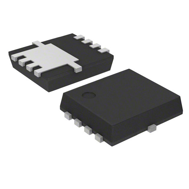
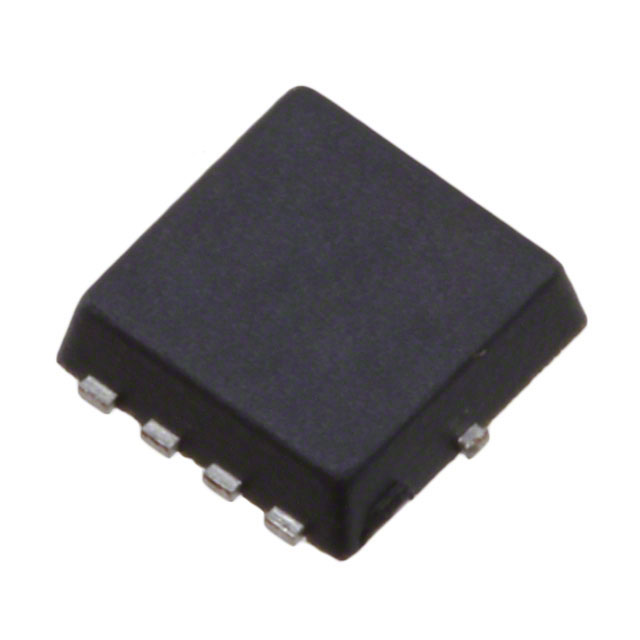
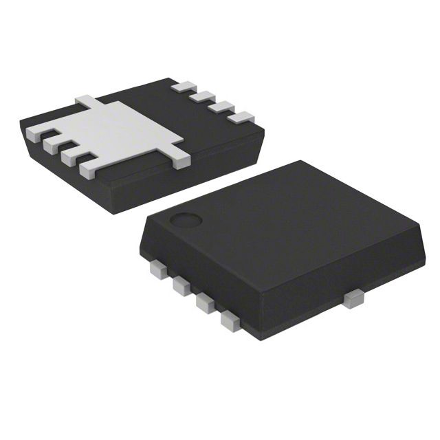
The AON6576 is an N-Channel MOSFET manufactured by Alpha & Omega Semiconductor Inc., rated for 30V drain-to-source voltage with continuous drain current of 26A (Ta) and 32A (Tc). The device is packaged in an 8-DFN (5x6) surface mount configuration and is designated as "Not For New Designs," indicating its status as a legacy component. Identification of equivalent and substitute parts is necessary for design continuity, supply chain flexibility, and compliance with current manufacturing standards.
Substiute Parts
Key Parameters
| Parameter | Value | Unit |
|---|---|---|
| FET Type | N-Channel | — |
| Drain-to-Source Voltage (Vdss) | 30 | V |
| Continuous Drain Current @ 25°C (Ta) | 26 | A |
| Continuous Drain Current @ 25°C (Tc) | 32 | A |
| Rds(on) Max @ 20A, 10V | 4.7 | mOhm |
| Gate Threshold Voltage (Vgs(th)) @ 250µA | 2.2 | V |
| Gate Charge (Qg) @ 10V | 27 | nC |
| Input Capacitance (Ciss) @ 15V | 1320 | pF |
| Power Dissipation Max (Ta) | 5 | W |
| Power Dissipation Max (Tc) | 26 | W |
| Operating Temperature Range | -55 to 150 | °C |
| Mounting Type | Surface Mount | — |
| Package | 8-DFN (5x6) | — |
| RoHS Status | ROHS3 Compliant | — |
| Moisture Sensitivity Level | 1 (Unlimited) | — |
Substitute Part Grouping Explanation
Substitution of the AON6576 is determined by electrical and mechanical compatibility across the following critical parameters:
Electrical Compatibility Criteria:
- Drain-to-Source Voltage (Vdss): Must equal or exceed 30V
- Continuous Drain Current: Must support minimum 26A (Ta) or 32A (Tc) operation
- Rds(on) characteristics: Must maintain acceptable on-resistance at specified gate voltage and current levels
- Gate threshold voltage and gate charge: Must be compatible with existing gate drive circuitry
- Operating temperature range: Must support -55°C to 150°C or equivalent thermal envelope
Mechanical Compatibility Criteria:
- Mounting type: Surface mount required
- Package footprint: 8-pin power package configurations (DFN, HSMT, TSON, SOP variants acceptable)
- Lead configuration: Flat leads compatible with standard PCB assembly processes
Compliance Criteria:
- RoHS3 compliance required
- Moisture Sensitivity Level 1 (Unlimited) preferred
- REACH unaffected status preferred
The substitute parts listed below meet these criteria with variations in package geometry, current ratings, and thermal characteristics that allow functional replacement in the AON6576 application space.
Parameter Comparison
| Parameter | AON6576 | DMT3004LFG-7 | RQ3E150BNTB | RQ3E180AJTB | RQ3E180BNTB | RQ3E180GNTB | TPH3R003PL,LQ | TPN4R203NC,L1Q | TPN4R303NL,L1Q |
|---|---|---|---|---|---|---|---|---|---|
| Manufacturer | Alpha & Omega | Diodes Inc. | Rohm | Rohm | Rohm | Rohm | Toshiba | Toshiba | Toshiba |
| Vdss (V) | 30 | 30 | 30 | 30 | 30 | 30 | 30 | 30 | 30 |
| Id (Ta) (A) | 26 | 10.4 | 15 | 18 | — | 18 | — | 23 | — |
| Id (Tc) (A) | 32 | 25 | 39 | 30 | 39 | 39 | 88 | — | 40 |
| Rds(on) Max (mOhm) | 4.7 @ 20A, 10V | 4.5 @ 20A, 10V | 5.3 @ 15A, 10V | 4.5 @ 18A, 4.5V | 3.9 @ 18A, 10V | 4.3 @ 18A, 10V | 4.2 @ 44A, 4.5V | 4.2 @ 11.5A, 10V | 4.3 @ 20A, 10V |
| Vgs(th) (V) | 2.2 @ 250µA | 3.0 @ 250µA | 2.5 @ 1mA | 1.5 @ 11mA | 2.5 @ 1mA | 2.5 @ 1mA | 2.1 @ 300µA | 2.3 @ 200µA | 2.3 @ 200µA |
| Qg (nC) | 27 @ 10V | 44 @ 10V | 45 @ 10V | 39 @ 4.5V | 37 @ 4.5V | 22.4 @ 10V | 50 @ 10V | 24 @ 10V | 14.8 @ 10V |
| Ciss (pF) | 1320 @ 15V | 2370 @ 15V | 3000 @ 15V | 4290 @ 15V | 3500 @ 15V | 1520 @ 15V | 3825 @ 15V | 1370 @ 15V | 1400 @ 15V |
| Pd (Ta) (W) | 5 | 2.1 | 2 | 2 | 2 | 2 | — | 0.7 | 0.7 |
| Pd (Tc) (W) | 26 | 42 | 17 | 30 | 20 | 20 | 90 | 22 | 34 |
| Tj Max (°C) | 150 | 150 | 150 | 150 | 150 | 150 | 175 | 150 | 150 |
| Package | 8-DFN (5x6) | PowerDI3333-8 | 8-HSMT (3.2x3) | 8-HSMT (3.2x3) | 8-HSMT (3.2x3) | 8-HSMT (3.2x3) | 8-SOP Adv (5x5) | 8-TSON Adv (3.1x3.1) | 8-TSON Adv (3.1x3.1) |
| Product Status | Not For New Designs | Active | Active | Active | Active | Active | Active | Active | Active |
| RoHS Status | ROHS3 Compliant | ROHS3 Compliant | ROHS3 Compliant | ROHS3 Compliant | ROHS3 Compliant | ROHS3 Compliant | RoHS Compliant | RoHS Compliant | RoHS Compliant |
| MSL | 1 (Unlimited) | 1 (Unlimited) | 1 (Unlimited) | 1 (Unlimited) | 1 (Unlimited) | 1 (Unlimited) | 1 (Unlimited) | 1 (Unlimited) | 1 (Unlimited) |
Engineering Selection Recommendations
Primary Substitutes for Direct Replacement:
The following parts are recommended as primary substitutes based on electrical parameter alignment and active product status:
TPN4R303NL,L1Q (Toshiba): This part provides the closest electrical match to the AON6576, with 40A (Tc) continuous drain current, 4.3 mOhm Rds(on) @ 20A/10V, and 34W (Tc) power dissipation. The 8-TSON Advance package (3.1x3.1) is smaller than the original 8-DFN (5x6) but maintains compatibility with standard surface mount assembly. Gate charge of 14.8 nC @ 10V is lower than the AON6576, reducing switching losses. Product status is Active with RoHS compliance.
RQ3E180GNTB (Rohm): This part offers 18A (Ta) and 39A (Tc) continuous drain current with 4.3 mOhm Rds(on) @ 18A/10V. The 8-HSMT (3.2x3) package is compact and suitable for high-density applications. Gate charge of 22.4 nC @ 10V is comparable to the AON6576. Product status is Active with full RoHS3 compliance and -55°C to 150°C operating range matching the original specification.
Secondary Substitutes for Higher Current Applications:
TPH3R003PL,LQ (Toshiba): This part supports 88A (Tc) continuous drain current with 4.2 mOhm Rds(on) @ 44A/4.5V, making it suitable for applications requiring higher current capacity. The 8-SOP Advance (5x5) package is comparable in size to the original 8-DFN (5x6). Power dissipation reaches 90W (Tc) with maximum junction temperature of 175°C. Product status is Active with RoHS compliance.
RQ3E180AJTB (Rohm): This part provides 18A (Ta) and 30A (Tc) continuous drain current with 4.5 mOhm Rds(on) @ 18A/4.5V. The 8-HSMT (3.2x3) package is compact. Gate charge of 39 nC @ 10V is higher than the AON6576, requiring consideration in gate drive design. Product status is Active with RoHS3 compliance.
Tertiary Substitutes for Lower Current Applications:
TPN4R203NC,L1Q (Toshiba): This part supports 23A (Ta) continuous drain current with 4.2 mOhm Rds(on) @ 11.5A/10V. The 8-TSON Advance (3.1x3.1) package is the smallest among substitutes. Power dissipation is 700 mW (Ta) and 22W (Tc). Product status is Active with RoHS compliance.
RQ3E150BNTB (Rohm): This part provides 15A (Ta) and 39A (Tc) continuous drain current with 5.3 mOhm Rds(on) @ 15A/10V. The 8-HSMT (3.2x3) package is compact. Gate charge of 45 nC @ 10V is higher than the AON6576. Product status is Active with RoHS3 compliance.
DMT3004LFG-7 (Diodes Incorporated): This part supports 10.4A (Ta) and 25A (Tc) continuous drain current with 4.5 mOhm Rds(on) @ 20A/10V. The PowerDI3333-8 package offers high thermal performance with 42W (Tc) power dissipation. Product status is Active with AEC-Q101 automotive qualification and RoHS3 compliance.
Selection Criteria Summary:
All substitute parts maintain 30V Vdss rating and surface mount configuration. Selection should prioritize parts with Active product status and current ratings meeting or exceeding application requirements. Package geometry differences require PCB layout verification. Gate charge and threshold voltage variations necessitate gate drive circuit evaluation. Thermal performance (Tc rating and package thermal resistance) must be validated against application heat dissipation requirements.
Frequently Asked Questions (FAQ)
Q: Can the AON6576 be directly replaced with any of these substitute parts without PCB modification?
A: Package geometry differences require PCB layout evaluation. The original AON6576 uses 8-DFN (5x6), while most substitutes use 8-HSMT (3.2x3), 8-TSON Advance (3.1x3.1), or 8-SOP Advance (5x5) packages. Footprint compatibility must be verified before implementation. Pin assignments are consistent across all N-Channel 30V MOSFETs in this category, but physical placement and thermal via requirements may differ.
Q: What is the primary reason the AON6576 is marked "Not For New Designs"?
A: The "Not For New Designs" status indicates the part is in end-of-life phase. Manufacturers typically apply this designation when transitioning to newer process technologies or when superior alternatives are available. All substitute parts listed carry "Active" product status, indicating current manufacturing support and long-term availability.
Q: How do gate charge differences affect circuit performance?
A: Gate charge (Qg) determines the energy required to switch the MOSFET on and off. The AON6576 specifies 27 nC @ 10V. Substitutes range from 14.8 nC (TPN4R303NL,L1Q) to 50 nC (TPH3R003PL,LQ). Lower gate charge reduces switching losses and allows faster switching speeds. Higher gate charge requires stronger gate drive capability. Gate drive circuit design must accommodate the selected part's Qg specification.
Q: Are all substitute parts RoHS compliant?
A: Yes. The AON6576 is ROHS3 compliant. All substitute parts carry either ROHS3 or RoHS compliance status, meeting environmental and regulatory requirements for commercial and industrial applications.
Q: What is the significance of Moisture Sensitivity Level (MSL) 1?
A: MSL 1 (Unlimited) indicates the component has no moisture sensitivity restrictions. Parts can be stored indefinitely without desiccant packaging and do not require baking before reflow soldering. All parts listed, including the AON6576 and all substitutes, carry MSL 1 rating, ensuring compatibility with standard manufacturing processes.
Q: How should I select between substitute parts with different current ratings?
A: Selection depends on application requirements. For applications requiring 26A (Ta) or 32A (Tc) operation, TPN4R303NL,L1Q (40A Tc) and RQ3E180GNTB (39A Tc) provide adequate margin. For lower current applications (under 20A), TPN4R203NC,L1Q (23A Ta) or RQ3E150BNTB (15A Ta) are suitable. For higher current applications (above 40A), TPH3R003PL,LQ (88A Tc) is recommended. Verify thermal performance against application heat dissipation budget.
Q: What thermal considerations apply when switching from the AON6576 to a substitute?
A: The AON6576 dissipates 5W (Ta) and 26W (Tc). Substitute parts vary: DMT3004LFG-7 dissipates 2.1W (Ta) and 42W (Tc); RQ3E180GNTB dissipates 2W (Ta) and 20W (Tc); TPH3R003PL,LQ dissipates 90W (Tc). Package thermal resistance differs across geometries. Verify that PCB thermal design (copper area, thermal vias, heatsinking) accommodates the selected substitute's power dissipation characteristics.
Q: Can gate drive voltage requirements differ between the AON6576 and substitutes?
A: Yes. The AON6576 specifies drive voltage at 4.5V and 10V. Substitutes maintain these drive voltage levels, but gate threshold voltage (Vgs(th)) varies. The AON6576 specifies 2.2V @ 250µA, while substitutes range from 1.5V to 3.0V. Gate drive circuits must provide sufficient voltage margin above the selected part's threshold voltage to ensure full enhancement and minimize Rds(on).
Q: Are there package size constraints that would eliminate certain substitutes?
A: Yes. The original 8-DFN (5x6) is 5mm × 6mm. Substitutes include 8-HSMT (3.2x3) — smaller; 8-TSON Advance (3.1x3.1) — smaller; 8-SOP Advance (5x5) — comparable; PowerDI3333-8 — larger. Space-constrained applications may require the smaller 8-HSMT or 8-TSON packages. High-power applications may benefit from the larger 8-SOP or PowerDI packages for improved thermal performance.
Q: What is the operating temperature range for each substitute?
A: The AON6576 operates from -55°C to 150°C (Tj). Most substitutes maintain this range: RQ3E180BNTB, TPN4R203NC,L1Q, and TPN4R303NL,L1Q all specify -55°C to 150°C or 150°C maximum. TPH3R003PL,LQ extends to 175°C maximum junction temperature, providing additional thermal margin. RQ3E150BNTB and RQ3E180GNTB specify 150°C maximum without lower temperature limit specification. Verify application temperature requirements against selected part specifications.
Q: How do Rds(on) specifications compare across substitutes?
A: Rds(on) directly affects power dissipation and heat generation. The AON6576 specifies 4.7 mOhm @ 20A/10V. Substitutes range from 3.9 mOhm (RQ3E180BNTB @ 18A/10V) to 5.3 mOhm (RQ3E150BNTB @ 15A/10V). Lower Rds(on) reduces conduction losses. However, Rds(on) is measured at different current and voltage conditions across parts, requiring normalized comparison at application operating points.
Alternative Parts

SJ6012L2TP
Littelfuse Inc.
6 Alternative Parts

JMK107BBJ476MA-RE
Taiyo Yuden
10 Alternative Parts

GMK107BBJ475MA-T
Taiyo Yuden
5 Alternative Parts
SJ6020N2ARP
Littelfuse Inc.
3 Alternative Parts
SJ6025R2ATP
Littelfuse Inc.
4 Alternative Parts

2474-05L
API Delevan Inc.
1 Alternative Parts

4590R-684K
API Delevan Inc.
1 Alternative Parts

CM6560R-334
API Delevan Inc.
1 Alternative Parts

CM6460-104
API Delevan Inc.
1 Alternative Parts

5526-12
API Delevan Inc.
1 Alternative Parts