


Request Quote
(Ships tomorrow)
AOD242 N-Channel MOSFET Equivalent & Substitute Parts
Part Overview
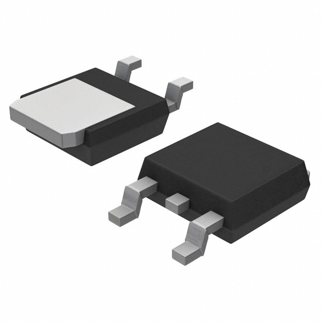
The AOD242 is an N-Channel MOSFET manufactured by Alpha & Omega Semiconductor Inc., rated for 40V drain-to-source voltage with continuous drain current of 14.5A at Ta and 54A at Tc. The device is housed in a TO-252 (DPAK) surface mount package and is designed for general-purpose switching applications. The AOD242 is classified as obsolete, making identification of functionally equivalent substitute parts essential for ongoing design support, production continuity, and component sourcing.
Substiute Parts
Key Parameters
| Parameter | Value | Unit |
|---|---|---|
| FET Type | N-Channel | — |
| Drain-to-Source Voltage (Vdss) | 40 | V |
| Continuous Drain Current @ 25°C (Ta) | 14.5 | A |
| Continuous Drain Current @ 25°C (Tc) | 54 | A |
| Rds(on) Max @ 20A, 10V | 5.8 | mOhm |
| Gate Threshold Voltage (Vgs(th)) @ 250µA | 2.3 | V |
| Gate Charge (Qg) @ 10V | 28 | nC |
| Input Capacitance (Ciss) @ 20V | 1350 | pF |
| Power Dissipation (Ta) | 2.5 | W |
| Power Dissipation (Tc) | 53.5 | W |
| Operating Temperature Range | -55 to 175 | °C |
| Mounting Type | Surface Mount | — |
| Package | TO-252 (DPAK) | — |
| RoHS Status | ROHS3 Compliant | — |
| MSL Rating | 1 (Unlimited) | — |
Substitute Part Grouping Explanation
Substitute parts for the AOD242 are selected based on strict electrical and mechanical compatibility criteria. All substitute candidates must satisfy the following requirements:
Mandatory Matching Parameters:
- FET Type: N-Channel
- Drain-to-Source Voltage (Vdss): 40V
- Mounting Type: Surface Mount
- Package: TO-252 (DPAK) or equivalent mechanical footprint
- Operating Temperature Range: Minimum -55°C to 175°C (or subset thereof)
Functional Compatibility Parameters:
- Continuous Drain Current (Tc): Equal to or greater than 54A
- Rds(on) @ 10V: Equal to or less than 5.8 mOhm (lower is acceptable)
- Gate Threshold Voltage: Within ±20V gate voltage specification
- Gate Charge: Comparable to minimize drive circuit redesign
Compliance Requirements:
- RoHS3 Compliant
- MSL Rating: 1 (Unlimited)
Substitute parts are grouped into two categories: direct replacements with minimal parameter variation, and higher-performance alternatives that exceed the AOD242 specifications while maintaining full backward compatibility.
Parameter Comparison
| Parameter | AOD242 | FDD8447L | FDD8453LZ | FDD9411-F085 | IPD50N04S4L08ATMA1 | IPD75N04S406ATMA1 | STD80N4F6 | STD120N4LF6 | STD95N4F3 | STD95N4LF3 |
|---|---|---|---|---|---|---|---|---|---|---|
| Manufacturer | Alpha & Omega | Fairchild | onsemi | onsemi | Infineon | Infineon | STMicroelectronics | STMicroelectronics | STMicroelectronics | STMicroelectronics |
| Vdss (V) | 40 | 40 | 40 | 40 | 40 | 40 | 40 | 40 | 40 | 40 |
| Id (Tc) (A) | 54 | 50 | 50 | 15 | 50 | 75 | 80 | 80 | 80 | 80 |
| Rds(on) Max @ 10V (mOhm) | 5.8 | 8.5 | 6.7 | 7.8 | 7.3 | 5.9 | 6 | 4 | 6.5 | 6 |
| Vgs(th) @ 250µA (V) | 2.3 | 3 | 3 | 4 | 2.2 | 4 | 4 | 3 | 4 | 2.5 |
| Qg @ 10V (nC) | 28 | 52 | 64 | 22.5 | 30 | 32 | 36 | 80 | 54 | 70 |
| Ciss @ 20-25V (pF) | 1350 | 1970 | 3515 | 1080 | 2340 | 2550 | 2150 | 4300 | 2200 | 2500 |
| Tj Max (°C) | 175 | 150 | 150 | 175 | 175 | 175 | 175 | 175 | 175 | 175 |
| Package | TO-252 (DPAK) | TO-252 (DPAK) | TO-252AA (DPAK) | TO-252AA (DPAK) | PG-TO252-3-313 | PG-TO252-3-313 | DPAK | DPAK | DPAK | DPAK |
| Product Status | Obsolete | Active | Obsolete | Active | Active | Active | Active | Active | Active | Active |
| RoHS3 Compliant | Yes | — | Yes | Yes | Yes | Yes | Yes | Yes | Yes | Yes |
| AEC-Q101 Qualified | — | — | — | Yes | Yes | Yes | Yes | Yes | — | — |
Engineering Selection Recommendations
Primary Substitutes (Closest Electrical Match):
IPD75N04S406ATMA1 (Infineon OptiMOS™) is the preferred substitute for the AOD242. This device matches the 40V Vdss specification, exceeds the 54A continuous drain current requirement at Tc with 75A capability, and delivers superior Rds(on) performance at 5.9 mOhm. The part maintains full operating temperature range (-55°C to 175°C), carries AEC-Q101 automotive qualification, and is in active production status. The lower on-resistance reduces power dissipation in switching applications.
STD80N4F6 (STMicroelectronics STripFET™ VI) provides an alternative with 80A continuous drain current and 6 mOhm Rds(on). This part is actively produced, RoHS3 compliant, and AEC-Q101 qualified. The higher current rating and lower on-resistance support higher-power applications while maintaining TO-252 package compatibility.
Secondary Substitutes (Acceptable Performance):
FDD8453LZ (onsemi PowerTrench®) offers 50A continuous drain current and 6.7 mOhm Rds(on), closely matching the AOD242 electrical profile. Although classified as obsolete, this part remains in inventory and provides near-identical performance characteristics. The higher gate charge (64 nC) requires verification of gate drive circuit capability.
IPD50N04S4L08ATMA1 (Infineon OptiMOS™) delivers 50A continuous drain current with 7.3 mOhm Rds(on) and is AEC-Q101 qualified. This part is suitable for applications where the 54A specification can be met with 50A operation.
FDD8447L (Fairchild PowerTrench®) provides 50A continuous drain current and 8.5 mOhm Rds(on). This active-status part is suitable for lower-power variants of the AOD242 application, though the higher on-resistance increases power dissipation.
Higher-Performance Alternatives (Exceeds Specifications):
STD120N4LF6 (STMicroelectronics DeepGATE™) and STD95N4F3 (STMicroelectronics STripFET™ III) both provide 80A continuous drain current with superior thermal performance (110W Tc). These parts are recommended for applications requiring enhanced thermal margin or higher current density. Both are AEC-Q101 qualified and actively produced.
Not Recommended:
FDD9411-F085 (onsemi PowerTrench®) is not recommended as a direct substitute. Although AEC-Q101 qualified and actively produced, the 15A continuous drain current specification falls significantly below the AOD242 requirement and is unsuitable for equivalent circuit operation.
Frequently Asked Questions (FAQ)
Q: Can the AOD242 be directly replaced with any of these substitute parts without circuit modification?
A: Yes, for most applications. All recommended substitutes maintain the 40V Vdss specification, TO-252 package compatibility, and surface mount mounting type. However, parts with significantly different gate charge (Qg) or input capacitance (Ciss) may require gate drive circuit verification to ensure adequate switching speed and efficiency. Verify gate voltage supply capability matches the ±20V specification.
Q: What is the primary reason for substituting the AOD242?
A: The AOD242 is classified as obsolete. Substitute parts are necessary to maintain design continuity, ensure long-term component availability, and support production requirements. Active-status alternatives provide equivalent or superior performance with guaranteed supply chain support.
Q: Which substitute offers the best thermal performance?
A: STD120N4LF6 and STD95N4F3 both deliver 110W power dissipation at Tc, compared to the AOD242's 53.5W. These parts are recommended for applications requiring enhanced thermal margin or operating at elevated ambient temperatures.
Q: Are all substitute parts RoHS3 compliant?
A: Yes. All recommended substitute parts carry RoHS3 compliance certification and MSL Rating 1 (Unlimited), matching the AOD242 environmental and moisture sensitivity specifications.
Q: What is the significance of AEC-Q101 qualification?
A: AEC-Q101 qualification indicates automotive-grade reliability testing and is required for automotive and high-reliability applications. IPD50N04S4L08ATMA1, IPD75N04S406ATMA1, FDD9411-F085, STD80N4F6, and STD120N4LF6 carry this certification. The AOD242 and FDD8453LZ do not list AEC-Q101 qualification.
Q: Can I use a substitute with lower Rds(on) than the AOD242?
A: Yes. Lower on-resistance is a beneficial characteristic that reduces power dissipation and heat generation. All recommended substitutes with Rds(on) values at or below 5.8 mOhm are directly compatible. Parts with higher Rds(on) values (such as FDD8447L at 8.5 mOhm) are acceptable but will increase power dissipation.
Q: What is the impact of higher gate charge (Qg) on circuit design?
A: Gate charge affects switching speed and gate drive power requirements. The AOD242 specifies 28 nC at 10V. Substitutes with higher gate charge (such as FDD8453LZ at 64 nC or STD120N4LF6 at 80 nC) require higher gate drive current or longer switching times. Verify gate driver capability before selecting these parts.
Q: Are there any package differences between the AOD242 and substitute parts?
A: All substitute parts use TO-252 (DPAK) or equivalent mechanical packages (TO-252AA, PG-TO252-3-313). These packages are mechanically and electrically interchangeable on standard PCB layouts. Verify footprint compatibility with your specific PCB design.
Q: Which substitute is recommended for new designs?
A: IPD75N04S406ATMA1 is recommended for new designs. This part combines active production status, AEC-Q101 qualification, superior electrical performance (5.9 mOhm Rds(on), 75A continuous current), and full operating temperature range support. STD80N4F6 and STD120N4LF6 are also suitable alternatives with active status and automotive qualification.
Q: Can I mix different substitute parts in the same production batch?
A: Electrical compatibility is maintained across all recommended substitutes. However, differences in gate charge, input capacitance, and threshold voltage may affect switching characteristics and thermal performance. For consistency in production and field performance, use a single substitute part number per design revision.
Q: What is the difference between Ta and Tc current ratings?
A: Ta (ambient temperature) represents continuous drain current at 25°C ambient with natural convection cooling. Tc (case temperature) represents continuous drain current with the device case maintained at 25°C through active cooling or thermal management. Tc ratings are typically higher and represent maximum device capability. Design calculations should use the appropriate rating based on your thermal management approach.
Alternative Parts

SJ6012L2TP
Littelfuse Inc.
6 Alternative Parts

JMK107BBJ476MA-RE
Taiyo Yuden
10 Alternative Parts

GMK107BBJ475MA-T
Taiyo Yuden
5 Alternative Parts
SJ6020N2ARP
Littelfuse Inc.
3 Alternative Parts
SJ6025R2ATP
Littelfuse Inc.
4 Alternative Parts

2474-05L
API Delevan Inc.
1 Alternative Parts

4590R-684K
API Delevan Inc.
1 Alternative Parts

CM6560R-334
API Delevan Inc.
1 Alternative Parts

CM6460-104
API Delevan Inc.
1 Alternative Parts

5526-12
API Delevan Inc.
1 Alternative Parts