


Request Quote
(Ships tomorrow)
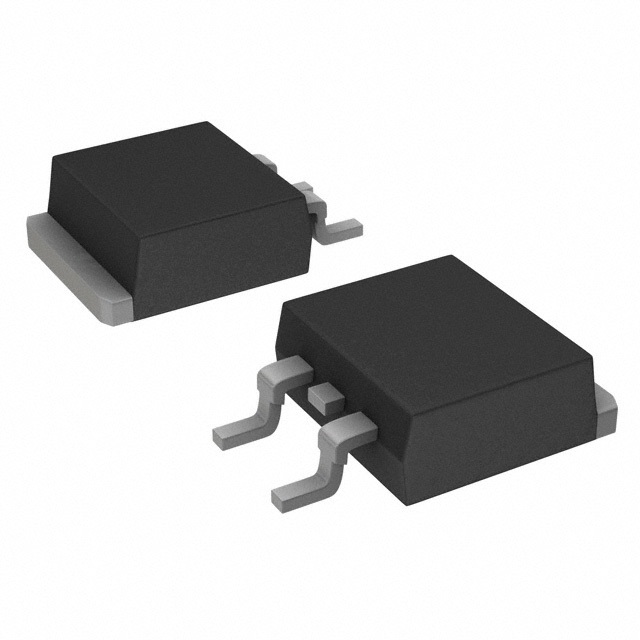
AOB442 N-Channel MOSFET 40V 21A/105A TO-263 Equivalent & Substitute Parts
Part Overview
The AOB442 is an N-Channel MOSFET manufactured by Alpha & Omega Semiconductor Inc., rated for 40V drain-to-source voltage with continuous drain current of 21A (Ta) or 105A (Tc) in a surface mount TO-263 (D2PAK) package. This device is part of the SDMOS™ series and is currently classified as obsolete. Due to its obsolete status, equivalent and substitute parts from active manufacturers are necessary for new designs and ongoing production requirements. Substitute devices must maintain compatibility with the TO-263 package footprint and electrical specifications within the defined parameter ranges.
Substiute Parts
Key Parameters
| Parameter | AOB442 Value | Unit |
|---|---|---|
| Drain-to-Source Voltage (Vdss) | 40 | V |
| Continuous Drain Current @ 25°C (Tc) | 105 | A |
| Continuous Drain Current @ 25°C (Ta) | 21 | A |
| On-Resistance (Rds On) @ 20A, 10V | 4.2 | mOhm |
| Gate Threshold Voltage (Vgs(th)) @ 250µA | 2.3 | V |
| Gate Charge (Qg) @ 10V | 90 | nC |
| Input Capacitance (Ciss) @ 20V | 5600 | pF |
| Power Dissipation (Tc) | 150 | W |
| Operating Temperature Range | -55 to 175 | °C |
| Package Type | TO-263-3, D2PAK | - |
| Mounting Type | Surface Mount | - |
Substitute Part Grouping Explanation
Substitution of the AOB442 is determined by strict adherence to the following electrical and mechanical parameters:
Critical Compatibility Parameters:
- Drain-to-Source Voltage (Vdss): Must equal or exceed 40V
- Package Type: Must be TO-263-3 or D2PAK (2 Leads + Tab) for mechanical and thermal compatibility
- Mounting Type: Must be Surface Mount
- FET Type: Must be N-Channel
- Technology: Must be MOSFET (Metal Oxide)
- Operating Temperature Range: Must encompass -55°C to 175°C
Performance Parameters for Functional Equivalence:
- Continuous Drain Current (Tc): Substitute must support minimum 105A at Tc
- On-Resistance (Rds On): Lower or equal values indicate improved performance
- Gate Charge (Qg): Lower values reduce switching losses
- Power Dissipation (Tc): Higher ratings provide thermal margin
All substitute parts listed meet the critical compatibility parameters. Differences in performance parameters reflect design improvements or trade-offs in the substitute devices while maintaining functional compatibility with the AOB442 application requirements.
Parameter Comparison
| Parameter | AOB442 | BUK764R0-40E,118 | BUK765R2-40B,118 | BUK964R4-40B,118 | IPB100N04S2L03ATMA2 | IPB80N04S4L04ATMA1 | IRF1404STRLPBF | IRL1404STRLPBF | IXTA160N04T2 | PSMN4R5-40BS,118 |
|---|---|---|---|---|---|---|---|---|---|---|
| Vdss (V) | 40 | 40 | 40 | 40 | 40 | 40 | 40 | 40 | 40 | 40 |
| Id @ Tc (A) | 105 | 75 | 75 | 75 | 100 | 80 | 162 | 160 | 160 | 100 |
| Rds On @ 10V (mOhm) | 4.2 | 4 | 5.2 | 4 | 3 | 4 | 4 | 4 | 5 | 4.5 |
| Vgs(th) (V) | 2.3 | 4 | 4 | 2 | 2 | 2.2 | 4 | 3 | 4 | 4 |
| Qg @ 10V (nC) | 90 | 54 | 52 | 64 | 230 | 60 | 200 | 140 | 79 | 42.3 |
| Ciss @ 25V (pF) | 5600 | 4405 | 3789 | 7124 | 6000 | 4690 | 7360 | 6600 | 4640 | 2683 |
| Power Dissipation Tc (W) | 150 | 182 | 203 | 254 | 300 | 71 | 200 | 200 | 250 | 148 |
| Operating Temp Range (°C) | -55 to 175 | -55 to 175 | -55 to 175 | -55 to 175 | -55 to 175 | -55 to 175 | -55 to 175 | -55 to 175 | -55 to 175 | -55 to 175 |
| Package | TO-263-3, D2PAK | D2PAK | D2PAK | D2PAK | PG-TO263-3-2 | PG-TO263-3-2 | D2PAK | D2PAK | TO-263AA | D2PAK |
| Product Status | Obsolete | Active | Active | Active | Not For New Designs | Active | Active | Not For New Designs | Active | Active |
Engineering Selection Recommendations
Primary Substitutes (Active Product Status):
The following devices are recommended as primary substitutes based on active product status and full compliance with electrical and mechanical requirements:
-
BUK764R0-40E,118 (Nexperia): Active product with AEC-Q101 automotive qualification. Rated 75A (Tc) with 4mOhm Rds On. Suitable for applications requiring automotive-grade reliability.
-
BUK765R2-40B,118 (NXP): Active product with AEC-Q101 automotive qualification. Rated 75A (Tc) with 5.2mOhm Rds On and 203W power dissipation. Provides enhanced thermal performance.
-
BUK964R4-40B,118 (Nexperia): Active product with AEC-Q101 automotive qualification. Rated 75A (Tc) with 4mOhm Rds On and 254W power dissipation. Offers superior thermal capability.
-
IPB80N04S4L04ATMA1 (Infineon): Active product from OptiMOS™ series. Rated 80A (Tc) with 4mOhm Rds On. Provides direct current capability match with lower gate charge (60nC).
-
IRF1404STRLPBF (Infineon): Active product from HEXFET® series. Rated 162A (Tc) with 4mOhm Rds On. Exceeds current requirements with significant thermal margin (200W).
-
IXTA160N04T2 (IXYS): Active product from TrenchT2™ series. Rated 160A (Tc) with 5mOhm Rds On and 250W power dissipation. Provides high current capability.
-
PSMN4R5-40BS,118 (Nexperia): Active product. Rated 100A (Tc) with 4.5mOhm Rds On. Lowest gate charge (42.3nC) and input capacitance (2683pF) among substitutes.
Secondary Substitutes (Not For New Designs Status):
-
IPB100N04S2L03ATMA2 (Infineon): Not For New Designs status. Rated 100A (Tc) with 3mOhm Rds On and 300W power dissipation. Acceptable for legacy system maintenance only.
-
IRL1404STRLPBF (Infineon): Not For New Designs status. Rated 160A (Tc) with 4mOhm Rds On. Acceptable for legacy system maintenance only.
All substitute devices maintain the TO-263 package family compatibility, operating temperature range of -55°C to 175°C, and 40V Vdss rating. Selection among active products depends on specific application requirements for current capacity, thermal dissipation, and gate charge characteristics.
Frequently Asked Questions (FAQ)
Q: Can the AOB442 be directly replaced with any of the listed substitutes?
A: Yes, all listed substitutes are mechanically and electrically compatible with the AOB442 within the TO-263 package family. Direct PCB footprint compatibility is maintained. However, thermal performance and current handling capabilities vary among substitutes, requiring verification that the substitute meets or exceeds the application's specific performance requirements.
Q: What is the primary reason for finding substitutes for the AOB442?
A: The AOB442 is classified as obsolete. Substitutes from active manufacturers ensure continued availability for production and new designs. Active product status guarantees ongoing manufacturing support, supply chain reliability, and compliance with current industry standards.
Q: Are all substitute parts available in the same package?
A: All substitutes use the TO-263 package family (D2PAK or PG-TO263-3-2 variants). These packages are mechanically and thermally compatible with the original TO-263-3 footprint. Pinout configuration remains identical across all listed devices.
Q: What is the difference between Ta and Tc current ratings?
A: Ta represents continuous drain current at ambient temperature (typically 25°C in still air), while Tc represents continuous drain current at case temperature (typically 25°C at the device case). Tc ratings are higher due to improved thermal coupling to the PCB through the D2PAK tab. The AOB442 specifies 21A (Ta) and 105A (Tc).
Q: Which substitute offers the best thermal performance?
A: BUK964R4-40B,118 provides the highest power dissipation rating at 254W (Tc), followed by IPB100N04S2L03ATMA2 at 300W (Tc). Selection depends on application thermal requirements and available PCB cooling area.
Q: Are automotive-qualified substitutes available?
A: Yes. BUK764R0-40E,118, BUK765R2-40B,118, and BUK964R4-40B,118 all carry AEC-Q101 automotive qualification from Nexperia. These are suitable for automotive and industrial applications requiring automotive-grade reliability.
Q: What is the significance of gate charge (Qg) differences among substitutes?
A: Gate charge affects switching speed and driver power requirements. Lower Qg values (such as PSMN4R5-40BS,118 at 42.3nC) reduce switching losses and simplify gate driver design. Higher Qg values (such as IPB100N04S2L03ATMA2 at 230nC) may require more robust gate drivers but do not prevent functional substitution.
Q: Can I use a substitute with lower continuous current rating than the AOB442?
A: No. The substitute must support at least 105A (Tc) continuous drain current to maintain functional equivalence. Devices rated below this threshold (such as BUK764R0-40E,118 at 75A) are not suitable for direct replacement in applications requiring the full 105A capability.
Q: What does "Not For New Designs" status mean?
A: Devices marked "Not For New Designs" are in end-of-life phase. While functionally compatible and available in limited quantities, they are not recommended for new product development. Active product substitutes are preferred for long-term design viability.
Q: Are all substitutes RoHS compliant?
A: All listed active substitutes are RoHS3 compliant. The AOB442 does not specify RoHS status. Compliance verification is recommended for applications subject to RoHS regulations.
Q: How do I verify that a substitute is compatible with my specific application?
A: Verify that the substitute meets or exceeds the following minimum requirements: Vdss ≥ 40V, Id (Tc) ≥ 105A, Rds On ≤ 4.2mOhm @ 10V, operating temperature range -55°C to 175°C, and TO-263 package compatibility. Additionally, confirm that gate charge, input capacitance, and power dissipation characteristics are acceptable for your gate driver and thermal management design.
Alternative Parts

SJ6012L2TP
Littelfuse Inc.
6 Alternative Parts

JMK107BBJ476MA-RE
Taiyo Yuden
10 Alternative Parts

GMK107BBJ475MA-T
Taiyo Yuden
5 Alternative Parts
SJ6020N2ARP
Littelfuse Inc.
3 Alternative Parts
SJ6025R2ATP
Littelfuse Inc.
4 Alternative Parts

2474-05L
API Delevan Inc.
1 Alternative Parts

4590R-684K
API Delevan Inc.
1 Alternative Parts

CM6560R-334
API Delevan Inc.
1 Alternative Parts

CM6460-104
API Delevan Inc.
1 Alternative Parts

5526-12
API Delevan Inc.
1 Alternative Parts